|
|
A Phototropic 2-motor Walker with
Sensors
A walker modified to follow light
by Wilf Rigter
In a June 2003 post, Wilf came forward with a circuit for a solar-powered light seeking walker based on an earlier solar walker design by Fred N!tr0_X.

Wilf's writeup on the circuit is as follows:
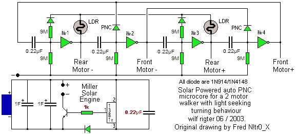
Here is the uCore Photo Bridge: a brand new way to influence a microcore walker with light sensors. I modified Fred's drawing, using cut and paste in my paint program, to incorporate the new circuit and also to point out a slight correction to the Miller Solar Engine.The uCore Photo Bridge:
The two Light Dependent Resistors in series form a ratiometric photobridge connected between Nv 1 and Nv 3 outputs which also control the rotation of the rear motor of a two motor walker. Depending on which Nv is active, the polarity across the bridge is reversed. When the two LDR sensors are the same resistance, the bridge is balanced and the midpoint voltage of the bridge is nominally Vcc / 2. If the two LDRs are not balanced, the midpoint will be offset from Vcc / 2.That midpoint voltage is the return point for the two new parallel timing resistors isolated with diodes and connected to the inputs of Nv 1 and Nv 3. Each parallel resistor and diode will affect the time constant of the corresponding active Nv depending on the voltage of the photo bridge midpoint.
When the midpoint of the LDR bridge is lower than Vcc / 2, the active Nv will time out faster. If the midpoint is higher, the active Nv will time out slower.
With an unbalanced photobridge, the midpoint voltage will be higher for one active and for the other the midpoint will be lower as the voltage across the bridge is reversed.
The parallel resistors remain active until the voltage of the timing capacitors on each Nv input drops below the photobridge midpoint voltage and the isolation diode becomes reverse biased. After that the original 9M resistor ensures that the Nv times out.
As a result the discharge voltage waveform of the active Nv will have a double slope, first steep with two resistors in parallel to discharge the capacitor and then slower with the single resistor to finish the capacitor discharge.
So why is this photobridge better than the "traditional" LDR in parallel with the microcore timing resistors arrangement? Most importantly it is relatively insensitive to the absolute light level, which in the traditional circuit would cause very short steps in bright light and long steps in dim light.
That problem of sensitivity to absolute light level also occurs in light seeking master slave bicore walkers. The uCore Photo Bridge only reacts to the ratio of the LDR resistance values and insensitive to the absolute light level. This makes the period of leg rotation relatively constant over a wide range of light levels.
This circuit comes piping hot from the mind of yours truly, so it is as yet untested but I think it will work spectacularly well. This may be an opportunity to test out this circuit and help develop into a tried and proven design.
|
|
|
|
|
|
||
|
|
This page was last updated on |
|