|
|
Quad Op-amp Walker Circuits
A family of circuits by Wilf
Rigter
In a November 2002 post, Wilf came forward with a phototropic walker design based loosely (see below) on Ben Hitchcock's "Not so dummy walker."

Wilf's writeup on the circuit is as follows:
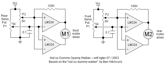
Speaking of Ben's "not so dummy" walker, here is the Not So Dummy Opamp Walker. Note the use of the swapped servo pots to drive each motor which is the key mechanism of this circuit.Using opamps makes it easier to trim the center position of each motor when the other motor should change direction. I added a small cap and some hysteresis to avoid false triggering from noisy servo pot wipers.
This walker maintains correct timing over a wide range of supply voltage (3V - 32V) because of the ratiometric comparator action of the "core". How about a 24V walker?
You can add all kinds of features to this circuit, such as dead band, turning and reversing. Interfacing sensors would be a snap because of the inherent accuracy of the opamps.
In a July 2003 post, Wilf further developed this design, enhancing it with reversing capability and the ability to track light.

Wilf's writeup on the circuit is as follows:
Here is the Quadrature Opamp walker with phototropic and reverser subsystems, the latter using some 74AC240 inverters (which limits the supply choice) Four of the remaining 74AC240 inverters could be used as motor drivers for the 6V Servo motors. The motors are driven with position feedback so sync reversing is not needed.All as yet untested but will probably work fine.
It was later pointed out to Wilf that the "Not so dummy walker" worked differently than he remembered, and that he had in fact invented a new type of walker circuit. Subsequently, Wilf expands on this:
The reference to the NSD walker in the Quadrature walker post was based on, what I mistakenly remembered as, the NSD walker's use of crossed-over servo feedback pots. I had not recently looked at nor ever really did an analysis of the Dummy and Not So Dummy Walker circuits, so this seemed good at the time.On closer examination it turns out the Dummy / NSD circuits are quite different in their use of the feedback potentimeters and are really unrelated to the Quadrature opamp design. It is however quite possible to do a Opamp version of the NSD walker.
You are quite right about the NSD walker's "only one motor on at a time" which gives the same stride as a microcore walker. If I had build the NSD walker or had seen a video (hint) of it walking that would have avoided the confusion.
I might add that the choice of two 6.8M resistors may not be optimum as it may not "unstuck" if the Schmitt hysteresis is Vcc / 3 (unlikely). However the RC delay can be much reduced by using a 6.8M feedback resistor with a 10M resistor across the coupling capacitor which may reduce the element of surprise but is also less wear and tear on the servo motors.
The Quadra walker evolved from the discussion of using feedback pots and opamps to sense the midposition of a leg for synchronous reversing. That led to the observation that in bicore walkers the midposition of one leg is the end of travel for the other leg etc. and therefore this accurate sensing of midposition of one leg can be used to change the direction of the other leg.
Therefore the Quadra walker uses the feedback pot of the second servo as a control signal for the first servo and vice versa. So if one leg gets stuck, its motor will eventually reverse as long as the second leg is not stuck since the stuck leg is controlled by the feedback pot of the second leg. Since two legs can be stuck at the same time, an RC time constant will be added to make Quadra walker smart about untangling itself from a sticky scenario.
The Quadrature opamp walker circuit, like the MS bicore walker, generates an efficient quadrature stride but uses true position feedback for springless leg centering.
Speaking of historical references: The Dummy Walker principle of using a Schmitt trigger to sense limits of travel from a servo feedback pot in order to reverse the direction of servo rotation was described in the uCrawler1.0 article of Oct 1999 on the old alt beam mailing list. The problem of "stalled" legs and the solution of using an RC delay to free the legs and using the same circuit for two motor walkers was also mentioned in the same article, reprinted here.
Those ideas were not explored any further until Ben posted his super simple Dummy and NSD walker designs with their innovative use of a 1 1/2 h-bridge motor driver, which by the way can be broadly applied to other two motor reversing driver designs where both motors are never active at the same time (i.e., a microcore).
|
|
|
|
|
|
||
|
|
This page was last updated on |
|