|
|
|
|
Tom Gray's Junkbot Walker
October, 2003
In "Junkbots, Bugbots, and Bots on Wheels," Dave Hrynkiw and Mark Tilden issued a challenge to the reader to expand on their Junkbot back-and-turn walker by making it "backup and turn for each side..., triggered by two different tactile sensors...turn left and right while going forward, chase light, scare the cat, take out the garbage, and deliver the mail."
This walker is my initial response to that challenge. It won't chase light, or handle the garbage and the mail, yet, but it frightens the cat and does turn left and right while going forwards or backwards.
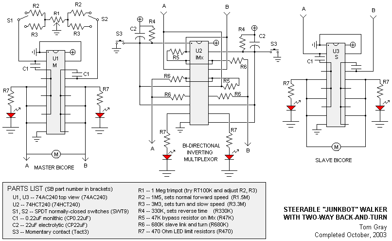
The trick to the turning part is to make deliberate use of an unbalanced bicore. Many newbies write to the BEAM list with the concern, "My walker won't go straight", not realizing that they are teetering on the edge of discovery. A balanced bicore will alternate left and right leg pulses equally. So to create a turn--in either forwards or reverse--you need a way to deliberately unbalance the bicore.
A few tests convinced me that the leading legs--the legs that are "front" whichever way the bot is moving--have the greatest turning effect. So if the bot is going forwards, throwing the front legs out of balance will initiate a turn; if the bot is reversing, throwing the rear legs out of balance will create a turn. Throwing front and back legs out of balance simultaneously will create a bot that flails and flips and turns belly-up, so there has to be a balance to the unbalance.
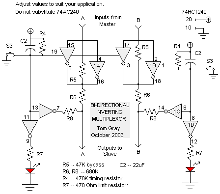
Let's start at the back. The Bi-directional Inverting Multiplexor handles the reverse. The inverters are normally disabled, and the Master bicore signal goes through the 47K bypass resistors R5 and the 680K link resistors R6 (the JB book has 620K here, but 680K worked better in my bot). The Master bicore fires and the Slave follows, making the front legs move before the back legs.
When either reverse switch S3 is triggered, several things happen. First, the capacitor C2 on that side is charged up (once S3 reopens, C2 gradually discharges through R4). But in the meantime...
a) One inverter in each pair is turned on, labeled 1A and 1B in the schematic. This changes the timing of the Master / Slave bicore pair, so that the rear legs now fire ahead of the front legs. The net result of this is that the walker backs up.b) 1D is enabled, which turns on the LED to tell you what's happening.
c) 1C is also enabled, and the additional 680K resistor R8 on the triggered side adds time to one part of the slave pulse and subtracts time to the other half of the pulse (okay, I'm guessing here!).
Anyway, the rear legs take a shorter, faster step with one foot and a longer, slower step with the other, and the net result of this is a turn towards the 'short step' side. And as a matter of some interest, if BOTH switches S3 are turned on simultaneously, the bot backs straight up very quickly. Neat to watch
The front unbalance is a bit clearer in the layout diagram. The SPDT switches are normally closed, and the Master bicore is controlled by the R2 pair (with R1 to balance for straight-ahead). Closing S1, for example, means that one half of the Master bicore oscillator goes through R3, which results in a longer, slower step for one front foot and a shorter, faster (normal) step for the other. Again, the result is a turn--a limping, faltering turn, but a turn for sure--towards the 'fast step' side. (Did I try it the other way, with the normal step being slow and the turning step being fast? Of course. The turn was the same either way, and I liked the fast walk better than the slow walk.) Turning on both forward switches BTW gives a slow, cautious forward creep. The bot looks like it is tentatively pushing against the obstacle.
A fair number of tests went into establishing that the 1:2 ratio (1M:2M or 1M5:3M3) gave the most effective combination of forward walk and forward turn. The bot will turn a circle in about 6 to 8 steps with a turning radius of about half a metre (18"). 1M:2M was a bit too fast, but 1M5:3M3 gives a limpy turn, and I haven't yet acquired a 1.2M:2.4M resistor pair. However, I think I will replace the two R3 resistors with a pair of 5M trimpots grounded in the middle to give a more precise way of setting the turn speed & radius.
Electronically, it works okay--but mechanically,
arranging the sensors so they worked together proved a
difficulty. Poor bot kept trying to back and turn and go
forward and turn at the same time. Ooop, belly-up! The next
incarnation will replace the mechanical reverse touch
sensors with IR detectors (from old VCRs...it is a junkbot!)
operating electronic switches. The 'forward turn'
tactile sensors will sweep out to the sides. Bot continues
to evolve...
|
|
||
|
|
This page was last updated on |
|