|
|
A Phototropic 2-motor Walker with
Sensors
A walker modified to follow light
by Wilf Rigter
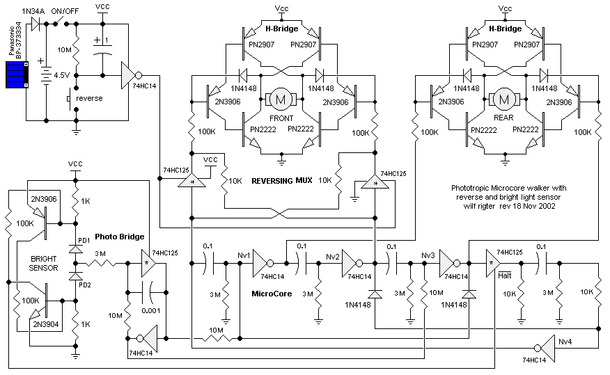
In a November 2002 post, Wilf presented a phototropic 2-motor walker design. Here's the circuit (double-click the diagram for a full-size version):

Wilf's writeup on the circuit is as follows:
I have modified the two motor walker posted earlier to include this feature [stops the walker when it gets to the light and moves back toward light when in shadow]. In addition I made a small correction to the auto PNC diodes which were not connected correctly in the earlier design.This circuit senses bright conditions by measuring the current that passes through two series photodiodes (PD1 and PD2). These photodiodes form a voltage divider that generates a control voltage at the midpoint of the two photodiodes. That voltage controls the photobridge circuit monocore so that it's output oscillates when the light is balanced. The photodiodes should be relatively low sensitivity or should be shadow masked to decrease their sensitivity.
To sense bright conditions both photodiodes must be strongly illuminated so that the total current through both increases above 0.3mA. That causes a 0.3V voltage across each 1K resistor which is sufficient to turn on the NPN and PNP transistors of the current sensor circuit. The resistors connected to the transistor collectors, when turned on, generate about an additional 1% extra base current through the 1K resistors. This is positive feedback that causes the bright sensor circuit to snap on. When the bright sensor 2N3904 transistor turns on, the collector voltage changes from +V to GND and this generates the active low Halt signal.
The Halt signal is used to tristate / disable the HC125 buffer in series with the Nv3 output. As a result the microcore outputs continue to pulse until Nv3 goes low and high again but the rising Nv3 output signal is blocked with the disabled HC125 buffer. A 10K resistor to GND at the 125 output holds the Nv4 input capacitor low. All microcore Nv outputs are now high (inactive) and both motors are stopped. In this state the circuit is in the standby mode and does not draw much power.
If the circuit is operated from a battery with on board PV solar panels, these must be lined up with the photo sensors to be pointed in the optimum direction for charging the battery while the light is bright.
When the ambient light level drops or a shadow is cast on the photodiodes, the current through the photodiodes drops and the bright sensor circuit rapidly turns off. The HALT line goes back to +V and the 125 buffer is enabled. The high level that was present on the Nv3 output is now gated through the HC125 to the Nv 4 input capacitor and starts the Nv4 pulse and the sequence of multiples of 4 microcore pulses before the next bright spot is encountered.
|
|
|
|
|
|
||
|
|
This page was last updated on |
|