|
|
The Servocore 2-motor walker
circuit
The Servocore walker electronics
(a 2-motor walker using un-modified hobby servos) by Wilf
Rigter
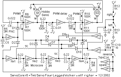
The original Servocore circuit indicated how a high frequency PWMcore could be modulated by a low frequency microcore central pattern generator. Straight from the idea cauldron, it required some time to digest (food for thought?). More than 2 years later here is a regurgitated uServocore version 5 complete with turn and reverse. It uses two 74HC14 chips and is rather more complex than its raw progenitor circuit. While still a thought experiment, the design incorporates an number of some interesting (innovative even) bits to point out.

PWMcore
= tricore
The PWM
loop is a tricore, a single delay stage separates the active
high PWM
pulses for both servos.
Microcore
to Bicore
translator
There is an advantage in using continuously active
PWM
signals. The main reason is that the asynchronous
frequencies of the PWMcore
and microcore
can sometimes result in a forshortened PWM
pulse. The Sevo reconizes this as a command for a new
positions and twitches toward that position. This makes the
motion somewhat jerky on the original uServo4 circuit.
In this application the microcore
is actually used as a quasi-bicore.
The microcore
outputs are connected through 4 diodes
to give the equivalent of master
/ slave
bicore waveforms but
with individual control of the rising and falling
phase angles. Since that can be used for turning a
conventional "bicore"
walker (but not the uServo walker), this technique may
be exploited in other walker applications as well.
Normally the microcore generates 4 individual pulses from Nv1 - Nv4. The master / slave bicore waveforms are two ovelapping quadrature waveforms. The translator synthesizes the bicore waveforms in two parts using diodes D3 - D8 to OR the microcore outputs. During forward motion the output of Nv 1 is not used So when Nv1 is active, the PWM pulses for both S1 and S2 are not influenced through diodes D3-8. and the PWMs generate the longest pulses driving both servos to CCW. When Nv2 is active it controls duration of the first half of the S1 CW position, Nv3 sets the second half of CW for S1 and the first half of CW for S2. Nv4 controls the second half of CW for S2.
Servo Rotation Sequence
The rotation sequence for the S1 and S2 servos is
controlled by the active high microcore
Nvs
as follows:
|
|
|
|
|
|
|
|
|
|
|
|
|
|
|
Reversing the walker
If the outputs of Nv1 and Nv3 can be alternately selected, that would provide a 180 degree phase shift of the PWM signals required to reverse the walker.
The microcore to bicore diode network also part of the reverse circuit to select whether the rear legs lead or lag by 90 degrees and therefore reverse the walker. The reverse circuit is a multiplexer to select either the output of Nv1 or Nv3 similar to the Mx circuit but using two 74HC14 inverters and diodes to "steer" Nv1 and Nv3 pulses and to set the reverse delay. During forward motion Nv1 output is blocked by D10 while the output of Nv3 is enabled by D9. Conversely when reversing, Nv1 output is enabled by D10 while the output of Nv3 is blocked by D9.
The rotation sequence for the S1 and S2 servos to reverse the walker is as follows:
|
|
|
|
|
|
|
|
|
|
|
|
|
|
|
The duration for the microcore Nv 1 - 4 pulses should be checked to be equal and slightly longer than the time for CW and CCW rotation. The 74HC14 diode multiplexer / reverser may be used for other microcore applicatons.
Turning the walker
A somewhat primitive turning circuit has
been used to add a left, right or
neutral bias on the rear motor PWM pulse
generator causing the walker to veer left, right or go
straight. The 1M pot (R9) is
adjusted the turning radius limited by the
stability of the walker. The next revision will use the
remaining spare inverters
for a more positive turning circuit
however for now, lest I suffer some serious mental
indigestion, that's it.
|
|
|
|
|
|
||
|
|
This page was last updated on |
|