|
|
The BEAM Circuits Collection is a BEAM Reference Library site.
74*14-based photopoppers
Nv-based, and other poppers --
all built on a common BEAM chip
To date, I've collected three 74*14-based circuits for photopoppers -- one (Dozer) by Darren Busson, based on one head circuit design (the Schmitt Comparitor Head, or SC Head), another circuit by Cliff Boerema based on yet another head circuit design, and a third circuit by John-Isaac Mumford.
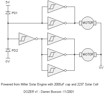
In November of 2001, Darren Busson posted that he'd played around with the circuit for the SC Head, and come up with a variant suitable for photopoppers. His result is simple, and as such, suitable for very small 'bots:

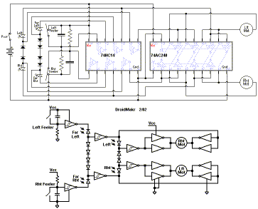
Droidmakr (Cliff Boerema) came up with an interesting idea for a light-tracking head with a form of peripheral vision. As often happens, the circuit turned into something different -- a photopopper:

Droidmakr's peripheral vision "roller" (click to enlarge)
Bruce Robinson posted this on the circuit:
1) Normal behaviour is both motors running "forward".2) When the robot is pointing in the general direction of a light, increased light on one of the "normal" photodiodes causes the motor on that side of the robot to stop. This causes the robot to pivot about the stopped wheel and face toward the light.
3) When "peripherial" photodiodes detect a difference between one side and the other, they over-ride the "normal" photodiodes. The photodiode that detects the brighter light reverses the motor on that side so the robot pivots sharply about its center (one wheel forward, the other reverse) to face more toward the light.
4) When the robot bumps into something on one side, it over-rides all the photodiode circuits and reverses the motor on the OPPOSITE side, causing the robot to pivot sharply away from the obstacle.
5) When both touch sensors contact an object, the robot backs up.
All done with a single 74HC14 (the '240 being a motor driver).
Meanwhile, Wilf Rigter posted this comment on its operation:
The behaviour of this circuit depends on the location of the photodiodes. From the title it would appear that all 4 photodiodes face forward but the 2 inner PDs face directly forward and the outer 2 are angled to the left and right. Then the effect is that the robot turns towards a light that is in directly in front by turning off one motor and pivots around the stopped wheel. But if there is a brighter light on the periphery (front left or front right) then the bot reverses one motor and the robot rotates around its center towards the light. So light in front only = small adjustment and brighter light to the side = rapid large adjustment. This effect of a strong peripheral light response mimics natural behavior.The tactiles switches behave even more strongly: if a switch is closed then the bot turns away unconditionally. If both switches are closed the robots reverse straight back regardless of light level.
In fact the behavior is even more complex and interesting as the light conditions themselves change with turning, etc. All in all, IMHO this circuit is destined to become a classic.
The multiple Si diodes provide a "dead band with memory" between one or two Schmitt inverters switching state. They are used as a constant voltage drop and can be replaced with LEDs, each of which has a higher forward voltage drop providing the same function as 2 or 3 series diodes.
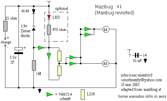
John-Isaac Mumford started off by simplifying the Maxibug design, and wound up with an entirely new circuit -- Mazibug (first posted in March, 2003):
I'vee used a zener diode and a 4148 diode in place of six 4148s. Then i removed the reverse function and cut down the inverter drivers for the motors and changed the biasing(?) resistor to 1M rather than the posted 1K. What you get is a robot which starts out photophobic, then when the voltage drops (to around 2.5v) it turns around and heads towards the light. All on one chip!
The size of the zener and cap should be modified to suit. I think solarizing might be a little difficult, but possible.
I tried the same setup with the 74*240 (with an extra inverter per motor) and 7404, but the 74HC14 seems to work best.
Wilf Rigter did a bit of tinkering, and turned this circuit into a more-efficient solarized 74*240-based critter documented elsewhere...
|
|
|
The discussion of the peripheral vision design
starts here;
Dave's redrawing came in this
posting. Cliff now has a page up on this 'bot on
his own site here. |
|
|
||
|
|
This page was last updated on |
|
