|
|
|
|
The BEAM Circuits Collection is a BEAM Reference Library site.
74*240-based photopoppers
Simple photopoppers, based on one
IC
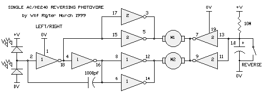
Back in the last century, Wilf drew up a nice design for a 74*240-based photopopper (basic photopopper functions plus reverse -- all on a single chip!) here:
In 2002, this design was resurfaced / reinvented on the Yahoo BEAM list. Here are Wilf's resulting sketches of 3 (non-reversing) circuits:
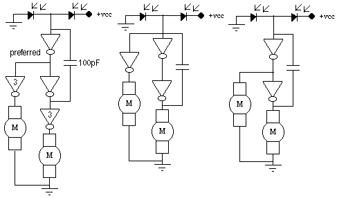
Note that in the first diagram, the inverters labeled "3" indicate that for each, 3 inverters are wired in parallel together. Wilf later added this explanation:
The monocore capacitor is for positive feedback for fast switching between the two motors and to slow down and avoid high frequency oscillations. With average light and 100pf, the frequency is 1KHz so there is a kind of vibration as each motor rapidly turns on and off. The overall effect is continuous rotation of both motors while moving straight towards the balanced light condition. Larger values will slow the oscillations so that each motor stays on longer (1 second on / 1 second off) and the motion is a "waddle" or even a twirling motion. With so much "overshoot" the motion will be somewhat random but the average direction should be towards balanced light. Try 1000pf or 0.01 uF for more purposeful motion.
In May of 2003, Wilf revisited this circuit again:
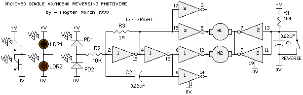
Wilf explains the circuit is as follows:
This is a revised reversing photovore schematic showing R2 and R3. The values of R2 and R3 are experimental and are related to the "resistance" of the photosensitive devices used in the photo bridge.R2 should be roughly equal to the minimum resistance of the the LDR, etc in bright light. If necesary these sensors should be shrouded or masked so that the current through them is not too high in bright light to avoid power losses. R2 together with C2 limits the maximum frequency of the monocore and motor drivers when the light is bright and the sensors are equally lit. That further avoids power losses as switching losses increase with frequency and motors don't respond very well to high switching frequencies (quivering).
R3 should be equal to the maximum resistance of the sensors in low light. R3 together with C2 sets the minimum frequency of the waggle even in the complete dark which is more interesting than twirling endlessly in a circle.
As I mentioned the values are experimental and should be adjusted for most interesting range of behaviour.
I also show alternative light sensors including 3 lead phototransistors used as photodiodes (AFAIK it is the collector base junction that acts as a reverse biased photodiode. This adapted photodiode is not as sensitive as large area types so C2 may need to be reduced to 0.01uF while the value of R2 and R3 can be increased by a factor of 10. Some LEDs can be used as photodiodes although these are less sensitive still.
Two leaded phototransistors can also be used but may require extra shielding to reduce light current in the bridge to acceptable levels. Note that here, sensitivity is less of a factor than dynamic range.
In March of 2003, Wilf turned John-Isaac Mumford's Mazibug into a 74HC240-based circuit he posted:
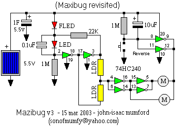
Try this 74*240 variation which uses an FLED for voltage detection and so is much more efficient. Of course this design asumes that there is enough light to charge and run the MAZIBUG at the same time (i.e. full Sun light). It is only when the cap is fully charged to 5V that it looks for shadows. When the cap is down to half voltage (about 2.5V), MAZIBUG searches out the light again. The spare inverters were used to add a reversing circuit.
Wilf followed up some more on the discussions of Maxibug derivatives, and came up with the "CD MaxiBug" in a March, 2003 post:
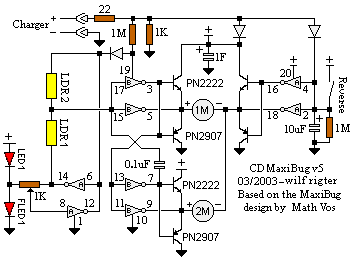
CD MaxiBug is based on the MaxiBug by Math Vos. If I had only taken some time to read his excellent tutorial in which he describes feeding stations etc, I would not have wasted my time reinventing the wheel. Having said that, maxibug is not perfect: it churns its wheels while feeding and does not back out of the feeding station when full. CD MaxiBug v5 uses just a few more parts but has powerful and efficient motor drivers, its motors are off while feeding, and it backs up when full.The CD Maxibug v5 uses just one 74AC240 chip. The motor drivers are of the Current Dump variety which do not waste any base current and can handle a wide range of motors. The voltage comparator uses two inverters with positive feedback to make a Schmitt trigger circuit. The 1K feedback potentiometer has a small value to control the LED current when changing state. A steady LED indicates low supply voltage and the phototropic mode. In addition, the comparator uses an FLED to provide efficient voltage sampling to minimize the 74AC supply current associated with a slow changing analog input voltage. Note that the Schmitt trigger configuration does not exclude the analog level from the input but does insure positive switching when triggered and reset.
MaxiBug is designed to work with a 5V feeding station that charges Maxibug's super cap used for energy storage. The cap must be rated 5.5V and is usually constructed with two equal capacitance 2.5V super caps connected in series to provide the voltage rating. The charging current is limited by a 22 ohm resistor in series with the feeding electrodes. A bright light beacon just above the feeding station electrodes is designed to attract and to line up MaxiBot's charging electrodes during the incoming trajectory. The physical design of the feeding station is up to the reader and will require considerable ingenuity to perfect. One consideration for "jacking" into the charger is to avoid closing the reverse switch when in the docking bay since that may cause it to back out before the charging contacts mate. Once contact is made MaxiBug v5 charging interface circuit applies +V to pin 19 and automatically turns off the B section motor drivers for a low power standby mode. The Maxibot charger interface circuit also charges the reverse delay circuit through a diode so that when the motors are turned on the MaxiBug will back up for the duration of the reverse delay.
The super cap charges up fairly rapidly while the storage cap voltage is monitored by the voltage comparator. The Maxibug v5 comparator is designed so that when the output is low, the feedback pot forces several milliamps of current through the reference LED to set the forward voltage to about 1.8V. The pot should be adjusted to set the trigger level close to 5.5V . Use a 6V supply (or battery) for the charging station. Turn the wiper of the feedback pot all the way towards the LEDs. When the cap is fully charged (~5.5V) slowly adjust the pot until the circuit triggers. Once triggered, the comparator applies a low voltage to pin 19 to enable the B section motor drivers and MaxiBug v5 disconnects from the charger and backs out of the feeding station.
When fully charged MaxiBug is photophobic and avoids bright light. The FLED and LED will both flash as the comparator samples the lower threshold voltage with each FLED current pulse. When the voltage drops to about 4V the comparator switches low again and LED turns on solid. MaxiBug now seeks out the beacon.
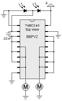
In August of 2003, Wilf posted an improved version of the "Bare Bones Photovore":
|
The BBPV is a little vulnerable to damage if a motor with too low resistance is connected to the first driver stage. That can cause the logic level on the second driver paralleled inputs (connected to first driver outputs) to be near the switching threshold. That can cause up to 200ma to flow through the second stage output stage and the circuit can self destruct from internal thermal overload. A slightly different design uses two inverters in series to process the photo input stage and uses the first and second inverter outputs to drive the respective parallel inputs of 2 groups of 3 inverters used as motordrivers. A small layout drawing is attached. The addition of the cap changes behaviour in different light conditions like the BeamANT. |
 |
|
|
|
Meanwhile, a more historic 74*240-based
photopopper design, the BEAMant, is documented on
its own page here. |
|
|
||
|
|
This page was last updated on |
|