|
|
The BEAM Circuits Collection is a BEAM Reference Library site.
555-based photopoppers
Simple photopoppers, based on one
IC
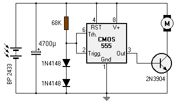
In March of 2003, Manfred Schaffran posted a solar engine design using a 555 timer IC:

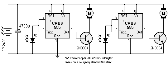
Wilf Rigter simplified this circuit a bit, made it phototropic, and doubled it up to yield a photopopper design in a post later the same day:

Wilf explains the circuit as follows:
The trigger level is about 3 times the photovoltaic output of the photodiode. You can add a series Si diode to raise the trigger level by 300mV (3x 100mV) . Since the photodiode voltage rises with the log of the light level, the photodiode voltage changes little over a large light range, making the trigger level and the "pop" relatively constant over light level. The 555 with the lower photodiode output voltage will of course trigger first. The cap should be sized to cause the motor to turn the bot no more than 45 degrees each pop -- any larger cap and the bot does "twirls".
In May of 2003, Wilf revisited this design in a subsequent post:

This is a new version that can use larger caps for longer pops by driving both motors at the same time but with a turning bias, which depends on the side triggered. The two diodes connect an active low output which drives a primary motor directly, also to the opposite motor. The diode drop reduces the voltage applied to the secondary motor so that it turns more slowly than the primary motor.
|
|
||
|
|
This page was last updated on |
|