|
|
BEAM From the Ground Up is a BEAM Reference Library site.
Connecting Nv nets
Getting in synch
The vast majority of Nv nets are either loops of Nv neurons, or several such loops connected together (given that a "loop" can consist of just 2 Nv neurons). Loops of Nv neurons are generally called "cores," and are described by a numeric prefix denoting the number of Nv neurons they contain -- Bicore (2), Tricore (3), Quadcore / Quadracore (4, the most common form), Quincore (5), Hexcore (6), Septcore (7), Octacore (8), etc.
|
As a general rule, connecting two cores together results in a synchronized group of circuits -- the fastest one causes the other(s) to synchronize to it. This "bossy" core (generally a bicore) is termed the "master," the others are termed "slaves."
The simplest set of Nv
loops -- the master / slave bicore pair
|
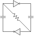
Let's start our mischief with a suspended bicore: |
|
|
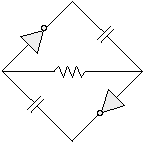
First, we'll rotate the diagram around a bit (note that this doesn't change anything in an electrical sense): |
|
|
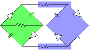
Next, we'll use the suspended bicore's outputs to wreak havoc on a second, grounded bicore (note that we're connecting the grounded bicore's resistors to the outputs of the suspended bicore's Nv neurons): |
|
This circuit is a master / slave bicore pair (often referred to in a fairly misleading shorthand as a "master / slave bicore"). Here, the suspended bicore is the master (green), and acts as a "pacemaker" for the whole circuit. The former grounded bicore is the slave (blue), and operates in a subservient fashion (but more on that in a bit).
|
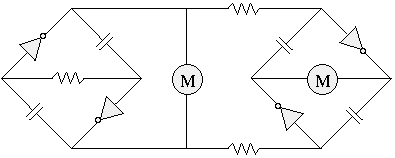
This circuit can then be applied to run a variety of things; the most common use is to drive a 2-motor walker: |
|
|
|
|
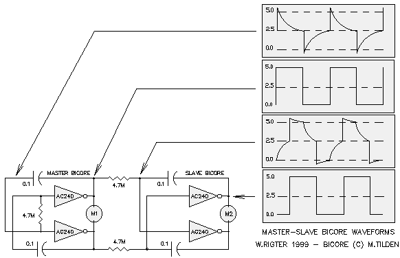 Assume a stable condition where: The outputs of the master are 1 and 0, Therefore the voltage across the slave coupling resistors (Vsr) = 0V and the voltage across the slave capacitors (Vsc) = 0V. Now assume the master bicore has just flipped it's bits. The master outputs are now 0 and 1, Therefore Vsr=Vcc and Vsc=0V and the slave capacitors start to charge / discharge through the "coupling" resistors. So far, no different from two Nu neurons (integrators) delaying a step input by their RC time constant. The slave inputs 1 and 0 charge towards opposite values and when either of the slave inputs reaches the switching threshold at approximately 1/2 Vcc, the corresponding slave output starts to switch from 1 or 0 to 0 or 1. Now feedback occurs, which is quite different from the Nu neuron and more like an Nv neuron. When the first output changes, this change is capacitively coupled into the other slave input and causes that input, already near 1/2 Vcc, to cross its threshold, which in turn causes the second output to change, which is capacitively coupled into the first input. The second RC node with the larger time constant plays no role in the timing of the slave bicore, and the RC components can be eliminated. This positive feedback results in an rapid voltage change at both slaves' input towards the value as the corresponding master outputs. During this rapid change, each slave capacitor charge is "dumped" through the slave input protection diodes so that the voltage across the caps and resistors rapidly changes to 0V. At that point the following stable condition exists: The master outputs are 0 and 1, The process repeats when the master bicore again flips its bits in the opposite direction. The formula for the delay time of a 74HC/ACxx slave bicore is approximately 0.7*R*C. The time constant of the master bicore is much trickier to calculate (especially when components are closely matched) since the switching threshold is close to 0V across the suspended resistor (i.e. on the flat part of the exponential discharge curve). This is what makes the master bicore time constant relatively-long for a given RC, and quite sensitive to preemptive triggering by "feedback" from the load. A rule of thumb used for determining the 74HC/AC04 or 74HC/AC240 type master bicore time constant is that it's approximately 1.4*R*C. Based on the requirement for 90 degree phase delay between master and slave bicore, the same RC components can be used in both. The 90 degree phase shift means that the
slave bicore's
output changes occur half-way in time between the
master bicore's
output changes. |
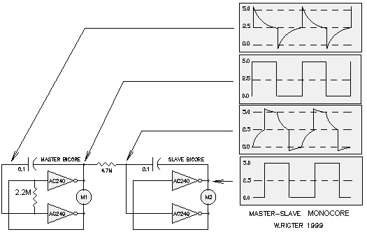
Meanwhile, what is (inaccurately) referred to as a monocore, is really just a master / slave bicore pair with a simpler connection than what we saw above:
|
|
|
John A. deVries II has written A rationale for a course of research into Nv Nets. Bruce Robinson has a fascinating site up on an
invention of his -- the Optically-Coupled
Bicore. |
|
|
||
|
|
This page was last updated on |
|

