|
|
BEAM Pieces is a BEAM Reference Library site.
Resistor part codes
Breaking the code
Through-hole resistors
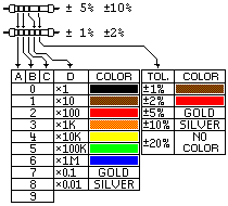
Most resistors you'll see are marked with a part code, in the form of colored bands painted onto the resistor. These can be read via a defined standard like this:

Let's make an example of this resistor: ![]()
First find the tolerance band, it will typically be gold or silver (in this case, it's silver).
Starting from the other end, identify the first band, and write down the number associated with that color. In this case the color is red, so you write down "2."
Now the next color is green, so write down a "5" (so far, you've got "25").
Now read the third or 'multiplier' band (blue = 1M) and multiply the value by it. Here, the indicated resistance value is 25 MOhm.
The tolerance band tells you how accurate the resistor's marked value is; here, it's silver -- so it's a 10% resistor (kinda' cheap). In all, this resistor will have a resistance of 25 ± 2.5 MOhm.
Note that 1% and 2% resistors will have 3 digits of resistance value.
Surface-mount
resistors
Based on a list posting by
Vincent Chin...
Some surface-mount resistors are marked with exactly the same color code as shown above for through-hole resistors. More often, though, surface-mount resistors are marked with a basic three symbol code -- the first two marked digits are the first two digits of the value, and the third digit is a multiplier (power of ten). This marking system is exactly the same as the marking system used for ceramic capacitors. All the values marked are in Ohms.
|
|
|
|
123 |
12000 Ohm / 12 KOhm |
|
122 |
1200 Ohm / 1.2 KOhm |
|
121 |
120 Ohm / 0.12 KOhm |
|
654 |
650000 Ohm / 650 KOhm |
A two symbol system is also occasionally used (although this is more common for capacitors). The first symbol in the two digit system is a letter representing a number value; the second symbol is the multiplier (power of ten). All the values marked are in Ohms.
A = 1.0
B = 1.1
C = 1.2
D = 1.3
E = 1.5
F = 1.6
G = 1.8
H = 2
J = 2.2
K = 2.4
L = 2.7
M = 3
N = 3.3
P = 3.6
Q = 3.9
R = 4.3
S = 4.7
T = 5.1
U = 5.6
V = 6.2
W = 6.8
X = 7.5
Y = 8.2
Z = 9.1a = 2.5
b = 3.5
d = 4
e = 4.5
f = 5
m = 6
n = 7
t = 8
y = 90 = x1
1 = x10
2 = x100
3 = x1000
4 = x10000, etc.
|
|
|
|
|
|
||
|
|
This page was last updated on |
|