|
|
|
|
BEAM Pieces is a BEAM Reference Library site.
Integrated circuits (ICs)
The ones you'll see most often in
BEAMbots
The following material is intended to cover usage and part selection details of ICs you're most likely to see in BEAM robots.
MC34164-*
 (image
courtesy of Solarbotics)
(image
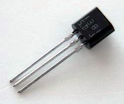
courtesy of Solarbotics)34164s are undervoltage sensing circuits ("voltage supervisors") designed for use as reset controllers in portable microprocessor based systems. We use them as 3- or 5-volt triggers (here, 3 or 5 fills in the "*" of the part number above), as the heart of the "Chloroplast" solar engine design.
See the data sheet for details on this chip.
1381*
(image
courtesy of Solarbotics)1381s are CMOS voltage-controlled triggers -- these "gate" a source until the voltage is above some "trip" limit, at which point it is allowed onto a third pin. These chips are discriminated by the voltage at which the 1381 triggers, with a single-digit suffix (a.k.a., its "rank") on the part number corresponding to the trip voltage:
Rank (suffix) Trip voltage (V) C 2.0 D 2.1 E 2.2 F 2.3 G 2.4 H 2.5 J 2.7 K 2.8 L 3.0 M 3.2 N 3.4 P 3.6 Q 3.8 R 4.0 S 4.2 T 4.4 U 4.6
The triggers operate in the range between the listed value and +0.2V (+0.3 from J up) above it (i.e.: a 1381C will trigger between 2.0 and 2.2V).
Generally, 1381*s are used to build very efficient solar engines, their job being to determine when the solar engine should "fire." The tradeoff in trigger value selection comes in that higher voltages lead to more-energetic activation, but at a less-frequent rate. The 1381J is the most commonly used, although of course, you can pick something different according to your needs. You can also use a diode in series with a 1381 to raise its trip voltage by 0.7 V.
1381*s generally come in the T0-92 package (see diagram above for pinout).
See the data sheet for details on this chip.
If you can't find 1381s locally, you might have better luck finding its European cousin, the TC-54 -- for details on it, see its data sheet.
 |
|
The 78M05 is one of a series of voltage regulator chips; this particular chip is popular among BEAMers since it takes a 5 - 35 V input, and outputs a nice, steady 5 V. This is very useful if you have a 'bot powered by a 9V battery (you'll need lower voltages to run most of your circuitry, since CMOS is designed to run on 5V or less). The 78M05 regulates output voltage to within 200 mV (i.e., it outputs 4.8 - 5.2 V). Unless you get a surface-mount variant of this IC, you'll be dealing with it in the T0-220 package (see diagram above for pinout).
Note that to get the most-reliable and most-efficient performance from this chip, you'll want to put filter capacitors across the power input and power output leads (according to the part specs, this is absolutely essential if either the power source or load is more than 6" from the IC).
See the data sheet for yet more details on this chip.
 |
 (image courtesy of Solarbotics) |
The 74*04 is, very simply, a package of 6 individually-accessible inverters (note that these are not Schmitt inverters, and as such have no hysteresis built into their response). As a result, this chip is just the ticket for building a suspended bicore. As it only outputs relatively low amounts of current, any *cores built with a 74*04 will require additional logic "downstream" to amplify the current to levels sufficient to drive a motor.
See the 74*14, below (which is essentially the same chip, but with Schmitt inverters). See also the 74*240, below (which is very similar to a 74*04, but with enables on outputs, and higher output current capability).
See the data sheet (one each for 74AC04 and 74HC04) for details on this chip.
 |
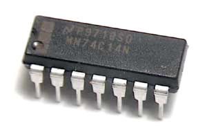
(image courtesy of Solarbotics) |
This chip is often considered the heart of Nv net technology, since each Schmitt inverter is individually-accessible (and so each, along with a capacitor, can be turned into a Nv neuron).
See the 74*04, above (which is the same chip, but with "vanilla" inverters, rather than Schmitt inverters). See also the 74*240, below (which is very similar to a 74*04, but with enables on outputs).
Note that Schmitt triggers can't easily be used in suspended bicore implementations (so save your '14s for non-suspended designs). As for flavors of 74*14 chips, a 74HCT14 Nv net has a longer pulse duration (given the same resistors and capacitors) than a Nv net built on a 74AC14 or 74HC14. Meanwhile, for ultra-low-power 5V - 12V applications for Nv, Nu, or oscillator circuits, use a 74C14.
See the data sheet for details on this chip.
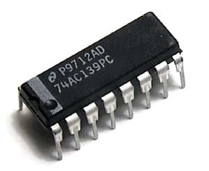 (image courtesy of Solarbotics) |
This chip was designed for demultiplexing data signals, but we ignore that and use its buffers as little current amplifiers. The 74*139 is good for turning into motor drivers.
See the data sheet for details on this chip.
 |
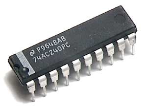 (image courtesy of Solarbotics) |
The '240 is often called "the bicore chip," because we can take advantage of the 240's inverters to turn a single 74*240 into a bicore (in this case, only 2 of the inverters are used, and the rest are used for upping the current so you can drive a motor directly). The '240 also has tri-state outputs, so an enable line can be used to turn its outputs on and off simply (good for adding reversing capability to a 'bot).
Since the '240 gives us "vanilla" (non-Schmitt) inverters, it is usable for either grounded or suspended bicore designs (but better for suspended). See also the 74*04, above (which is very similar to the 74*240, but without tri-state outputs, and with about half the output current capabilities), and the 74*244, below (which is basically a '240 with non-inverting buffers).
Note that pins 1 and 19 are the enable (tri-state control) pins. Signals on these pins pass through an inverter before getting to the buffer's tri-state control terminals, which means that a low voltage at 1 & 19 would be a high voltage at the buffer, so the buffer would be enabled. A high voltage on those pins would be a low voltage at buffer's tri-state controls and would turn the buffers off. So tie pins 1 and 19 to ground to enable all of the inverters inside the '240 chip.
Words of wisdom from Wilf:
74HC240 and similar HC buffers
- Vcc=2V-7V but will operate down to 1.0V or less, input
voltage trigger / switching level about 1/2 of Vcc, supply
current
when one input is at switching level = 50 ma (power hungry
during slow switching), 30 ohm resistance in series with
output with Vcc=5V. Drives small motors. Can give very long
bicore time constants if components are carefully matched.
Recommended for power smarthead / monocore
circuits
since time constants remain relatively constant with change
in Vcc.
74HCT240 - same as 74HC240 but with "fixed" input switching point of about 1.6V. Faster bicore frequency with same components as HC circuit.
74AC240 and all other AC devices - same as HC but about 10 ohm series output resistance. Three times drive current of HC, draws over 100 ma power supply with input at switch point. Prone to oscillation. No problems / low power when used with fast changing digital input signals and highest efficiency for motor (100 ma) driver applications.
74ACT240 - same as AC but fixed input switching level.
A 74HCT240 Nv net has a shorter pulse duration (given the same resistors and capacitors) than an Nv net built on a 74AC240 or 74HC240.
See the data sheet for details on this chip.
 |
(image courtesy of Solarbotics) |
The '244 provides us with 8 (thus the "octal") buffers, enableable in banks of 4. This is a very useful chip for amplifying small currents (and so, it is often used to build up motor drivers). Since the '244 has 8 buffers (i.e., 8 current "amplifiers"), it can drive up to 4 motors in 2 directions each, or you can "buddy up" inputs and outputs to drive fewer motors at higher current.
See also the 74*14, above (which is very similar to the 74*244, but with inverting Schmitt triggers), the 74*240, above (which is basically a '244 with inverting buffers), and the 74*245, below (which is much like the '244, but allows for amplification in both directions).
As with the 74*240, pins 1 and 19 are the enable (tri-state control) pins. Signals on these pins pass through an inverter before getting to the buffer's tri-state control terminals, which means that a low voltage at 1 & 19 would be a high voltage at the buffer, so the buffer would be on. A high voltage on those pins would be a low voltage at buffer's tri-state controls and would turn the buffers off. So tie pins 1 and 19 to ground to enable all of the inverters inside the '244 chip.
See the data sheet for details on this chip.
 |
 (image courtesy of Solarbotics) |
The '245 is an octal buffer chip, and so has 8 channels of buffering power available for our misuse. This chip was designed for data transmission uses, but we'll misuse it as a motor driver chip (each buffer essentially amplifies current ) to drive motors from Nv net signals (80 ma per channel). Since the '245 has 8 buffers (i.e., 8 current "amplifiers"), it can drive up to 4 motors in 2 directions each, or you can "buddy up" inputs and outputs to drive fewer motors at higher current.
If you need even more current,
you can stack '245s, like so: ![]()
If you plan on "pushing" your stacked chips' current outputs close to their limits, you should attempt to get an "air-gap" between the chips (put a thin sliver of cardboard between the chips when you solder them together).
For maximum drive current output, you'll want to use the AC / ACT "flavors" of this chip (use ACT only if you have well-regulated 5V power available in your circuit). Note that if you need more than about 200 mA per motor, you'll need to use an H-bridge, or some similar motor driver, in conjunction with (or instead of) this chip. Let's compare output current capabilities:
- 74HC245 -- 35 mA per output; maximum of 75 mA per chip
- 74AC245 -- 50 mA per output; no maximum per chip
The *245 is good for 2-motor walkers; if you want to build a walker with more motors, or one capable of reversing, some folks prefer to use the 74*244 instead.
See the data sheet for details on this chip.
Miscellaneous usage guidelines from Wilf:
- 74HC/HCTxx non-buffers
(74HC14 or 74HC04) draw about half of the current
consumption, and have about half the drive current
compared to HC / HCT buffer
chips (74HC240 or 74HC245). Non-buffer
chips are thus better for oscillators, say Nv
and Nu
applications; they are not suited for use in driving
motors.
- For 4000 or 74Cxx CMOS (i.e. 4069 or 74C14), Vdd= 3V
to 12V. These are used for low power oscillators,
bicores,
voltage comparators, and threshold detectors at 5V. At
3V, these can be used for similar applications with low
drive current.
CD4049 and CD4050 can drive small loads similar to
74HC/HCT non buffered
parts.
- For ultra low power applications (low light solar
bots) use discrete components or 4000 CMOS combined with
the high output current
capability of discrete MOSFET H-bridge or 74AC / ACT
motor drivers for best overall efficiency.
- In general power consumption and drive vary directly
with Vcc; save TTL-level logic for problems that
absolutely demand it. For an "average" Nv
net, the current at 3V supply is 10x less and at 2V
it is 100x less compared to the same chip used at 5V.
- The ideal BEAM
circuit would use a low (2V-3V) voltage core and sensors
combined with level shifting high (5-6V) volt motor
drivers to maximize efficiency.
- For motor driver applications connected to heavy
loads such as motors or coils, use 74ACxxx for increased
current
capability. For most Nv
/ Nu
applications with outputs connected to LEDs, other chip
inputs or to motor drivers,
74HCxxx is recommended. The flip-side of this is that
74ACxxx used in typical BEAM applications uses 4x more
supply current
than does 74HC/HCTxxx.
- 74HC/ACxxx have input trigger levels that are
symmetrical and near the midpoint of the power
supply.
- 74HCT/ACTxxx have trigger levels that are not
symmetrical (except near about 3V) and do not track the
supply voltage.
- 74HC/AC240, 244,
540, 544 chips (and numerous others) can all be used as
motor drivers
in exactly the same way, observing the differences in
pinouts of course. In addition the 74HC/AC241/541 octal
buffer has complementary tristate enable pins (1 and 19 -
one active high and one active low), which can save an
inverter in some reverser applications.
- The 74HCT/ACT bicore has a more predictable time constant and is not as sensitive to motor feedback (if that's desirable). For all other Nv / Nu applications the HC/AC version is generally preferred.
As a general rule, you'll want to stay away from TTL-level logic (74*TXXX chips) unless you're prepared to deal with well-regulated 5V power supplies.
AC logic is much faster that HC, has higher gain, and most members of that family (except 74AC14/132) will emit bursts of high frequency oscillation and draw high supply current pulses (>100ma) when operated in quasi-linear (especially Nu) BEAM circuits. At times this causes some difficult to understand or strange symptoms. 74AC is best suited for motor driver applications with all inputs driven rail to rail. Even if used for digital applications, spurious noise and oscillation must be controlled with good circuit layout, signal / supply line routing and supply pin filtering. This has be known to digital circuit designer for a long time and you never see all-74ACxxx designs. Chip manufacturers have come up with newer advanced BI-CMOS logic families which control switching transients but are generally not suitable for BEAM applications.
Many thanks to Wilf Rigter for helping me figure most of this out; as usual, though, complaints, comments, and harangues should be directed to this page's maintainer.
|
|
||
|
|
This page was last updated on |
|