|
|
The BEAM Circuits Collection is a BEAM Reference Library site.
The "Miller" solar engine
Yet another way to use a 1381
voltage detector
The Miller solar engine uses a 1381* voltage detector (a.k.a., a voltage supervisor) IC to drive a voltage-based (type 1) solar engine. The 1381 is normally used to reset CPUs and Micros when the power supply drops too low for reliable operation. So 1381s detect and switch when the input voltage crosses the rated upper and lower threshold voltages. The upper- and lower-switching voltages are slightly overlapped so that the turn-on voltage is a few hundred mV above the turn-off voltage. This hysteresis keeps input noise (around the switching threshold) from resulting in multiple output cycles as the transition occurs.
The Miller SE is designed to increase the 1381 hysteresis to a larger value. This is done by putting a small capacitor across the input legs of the 1381, and a diode between the 1381 and the "true" ground.
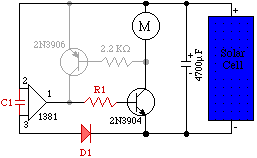
Here's the basic circuit (I show it as a modification to the "vanilla" 1381 circuit, where added components are red, deleted components are grayed out, and common components are in black):

How it works
As the solar cell charges the (4700 uF) storage capacitor, the voltage across the capacitor increases with time. Eventually it reaches the 1381's trip point, and the 1381 applies voltage to the base of the 2N3904. Since this is an NPN transistor, it "trips" and applies current to the motor. This state of affairs will continue until the 1381 sees a voltage that looks like its trip point less 0.3 V, at which point the 2N3904 goes "quiescent," and the solar cell resumes charging the storage capacitor.
By choosing values for C1 and R1, we can "tweak" the performance of this circuit. If the load is (as shown above) a motor, we'll want R1 to be zero (i.e., no resistor), and C1 to be about 0.47 uF. Larger values for C1 result in longer (but less-frequent) "bursts" of motor activity; smaller values result in shorter (but more-frequent) activity. Larger values of R1 reduce the power going through the motor, as well as lengthening the "bursts" of motor activity. If the load is an LED or something similar, you'll need less power to drive it, and probably then want a non-zero value for R1.
|
|
|||
|
|
|
|
|
|
Storage capacitor |
|
|
|
|
|
|
|
|
|
0.47 uF capacitor |
|
|
|
|
Diode (small signal) |
|
|
|
|
|
|
|
|
|
|
|
|
|
|
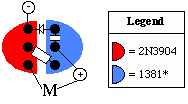
Freeforming Start by glueing the 2N3904 and 1381 together ("face to face"). As is usual for things this small, you should then solder your connections starting in the middle (i.e., work your way out). |
 |
|
|
|
Jérôme Demers has a page up on the Miller SE -- with pictures of the circuit as built on a breadboard -- here. A quick rundown on the history of the Miller SE
design was posted here. |
|
|
||
|
|
This page was last updated on |
|