|
|
The BEAM Circuits Collection is a BEAM Reference Library site.
The MicroPower SE
Ken Huntington's contribution to
the SE canon
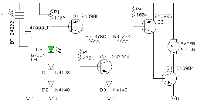
Ken Huntington's "micropower" solar engine is described here (the following writeup comes from Steve Bolt's web pages -- 1 image, 6 kBytes inline):
A 'micro power solar engine' has been a goal since my introduction to BEAM Robotics. I believe that if there wasn't one before, I there is one now. What I'm presenting to you looks very similar to one of the circuits found in Steven Bolt's web pages. As you will see, I made only minor changes to that design and not without help. My contributions have been to recognize the potential of the circuit , bread board and test it. The bottom line is that if you have a power source which will provide 2.5Vdc at 10uA this circuit should drive a pager motor. It turns on the motor at 2.3 to 2.5Vdc and switches off at 1.2 to 1.5Vdc.

Both Steve and I have built (bread boarded or haywired) the business end of the design and achieved similar results. This does not mean that it will work for everyone but it should. [I used a BC559C (Q1), a BC549C (Q2) a BC559B (Q3) and a BC337-25 (Q4), which happened to be in the bitbox. SB]There is one adjustable resistor which is the only real complication and it means that there is a calibration procedure which is as follows:
- Set R1 to max.
(1.0M).
- Connect a DVM across
the storage capacitor
.
- Enable power to the
circuit
. If the circuit
works properly, the
voltage will rise to a firing point, turn on the motor
momentarily which discharges the capacitor
to level where motor has
little current
passing through it but Q1
and Q2 are still conducting. At this point,...
- Slowly adjust R1 until
the voltage starts to rise again. This is the threshold
for minimum operation.
- Adjust R1 just a
little further to assure reliable operation.
In practice, I removed R1, measured its value and replaced it with a standard resistor value 5 to 10% less. 560K was the value that both Steve and I used which shows just how repeatable this design is or how lucky we were.
Note: It is realized that this presentation is very cryptic. If it were delayed until a complete circuit description and circuit layout were complete, it may not have been presented at all. It is hard for many to realize the time and effort it takes to create the circuit cards, obtain the correct parts, make up the kits and write assembly / debug instructions. The dollar cost and other risks are not minimal.
If there is a need for this circuit , it shall come to pass.
KG
A layout has recently been published by Eric Platt, he r e, which also shows a nice photo of the very compact result.
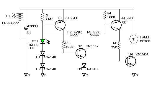
Ken later updated the design as follows:

And here are Ken's comments (slightly edited) on the design changes:
There have been two optional changes.The first results from building a number of units. It was found that R1 could be replaced with a 680K resistor rather than using a pot. R6 was added to limit the current used to drive the base of Q4 which meant that more current became available for the motor. 390 Ohms is the smallest value that should be used for R6, it can be larger depending upon the motor and drive transistor (Q4) combination.
There is one further proposed change that could improve the overall efficiency but it has not been tried, as far as I know. Changing Q4 to a ZTX618 improves the voltage across the motor. It is manufactured by Zetex and available from Digi-Key, but the trouble and the price ($1.08 US) may just not be worth it.
|
|
||
|
|
This page was last updated on |
|