|
|
The BEAM Circuits Collection is a BEAM Reference Library site.
FLED-based solar engines
Flashing your way to a solar
engine
The original FLED-based SE uses a flashing LED to drive a type 1 solar engine (you'll note that it's just like the Zener-based SE, but with a FLED in the starring role). The good news is that all the parts in this solar engine are relatively easy to find; the bad news is that this solar engine design isn't particularly efficient unless you work at it.
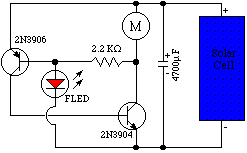
Here's the (original) basic circuit:

The idea here is that when the FLED flashes (at about 2.4 volts), it conducts. This makes the base of the PNP transistor (here shown as a 2N3906, but you could also use a BC327) go "low," so it triggers, which makes the base of the NPN transistor (here shown as a 2N3904, but you could also use a BC337) go "high," and when it triggers, current is applied through the motor. Note that once the NPN transistor triggers, the FLED is essentially out of the circuit; the motor is then given power until the transistors go inactive at about 0.7 V.
Wilf Rigter contributes this more-detailed explanation:
The FLED is a integrated circuit that needs a minimum voltage to operate and flash the LED. While the LED is off the current through the FLED is very low. When the LED is on, a pulse of current passes through the FLED.The solar cell charges the main capacitor until the voltage is high enough for the FLED to start flashing. When the FLED flashes, current flows through the FLED and the base of the PNP transistor and it turns on. Now current passes through the PNP into the base of the NPN transistor and it turns on. When the NPN turns on the collector which is connected to the motor and the 2.2K resistor goes low (to GND). This places a voltage across the 2.2K resistor which provides more base current for the PNP transistor which make it turn on even more. That is called positive feedback or latching of the circuit because both the PNP and NPN transistors remain on untill the main capacitor is discharged to less than 0.7V. When the capacitor voltage drops below 0.7V the PNP and NPN transistors both turn off because of the minimum voltage required to keep the base emitter turned on.
The 2.2K resistor sets the base current for the PNP to about 1 mA, which is amplified by the beta (current gain) of the PNP by 50-100.
That 50 mA of current flows into the base of the NPN and is amplified by about 10 to drive the motor. As long as the motor draws no more than 500 mA this circuit will work fine. If the motor current is much less, then increase the resistor value correspondingly. If the motor draws more current then uses a smaller resistor. Be sure to use a PN2222 or equal for the NPN for current greater than 200 mA.
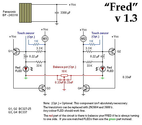
An improved (for lower power consumption) version by Ben Hitchcock is here:

Ben's circuit is presented here in two, twin, copies. If you're building a photopopper, build it just the way Ben presents it. If you're building a symet or ornament with this SE, just build half of what's in Ben's diagram.
As for the basic circuit, Ben has improved the efficiency of the solarengine through the addition of just two components -- a 0.22 uF capacitor, and a 33 KOhm resistor (he's also upped the basic FLED SE's 2.2 KOhm resistor to a 3.3 KOhm resistor, but that's beside the point).
|
|
|||
|
|
|
|
|
|
Storage capacitor |
|
|
|
|
|
|
|
|
|
3.3 KOhm resistor |
|||
|
33 KOhm resistor |
|||
|
0.22 uF capacitor |
|||
|
Red FLED |
|||
|
|
|
|
|
|
|
|
|
|
Ben's use of this circuit for a photopopper takes advantage of an interesting feature of FLEDs -- they are photo-sensitive. In particular, light shining on a FLED causes that FLED's SE to be inhibited (to perform more poorly). So if you're building a phototropic FLED -based BEAMbot, you may have problems in bright light (both SEs in your 'bot are being inhibited, so neither side of your 'bot wants to fire) -- you can address this by partially shielding your FLEDs with heat-shrink tubing, or some paint (be careful here, you're trying to give your 'bot sunglasses, not blinders). Meanwhile, if you're using a FLED-based SE on a non-phototrope, you'll want to completely cover the FLED (with heat-shrink tubing, or black electrical tape, or dark paint...).
|
|
|
|
|
|
||
|
|
This page was last updated on |
|