|
|
The BEAM Circuits Collection is a BEAM Reference Library site.
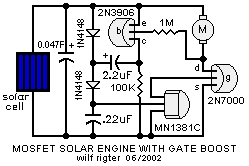
The GBSE (gate boost solar engine)
Another Wilf Rigter design,
described in his own words
The Gate Boost SE uses a 1381, a 2N7000 MOSFET and a 2N3906 with a unique voltage doubler to increase the voltage applied to the gate of the MOSFET. Normally the 2.6V output of a 1381C is barely able to turn on the 2N7000. As a result the "on resistance" of the MOSFET is high and much power is wasted.

The 2N7000 works very well with 5V or 6V gate drive and then has an "on resistance " of a few ohms.
The Gate Boost SE uses a voltage doubler to pump up the voltage of the 0.22 uF capacitor after the 1381C has triggered.
How it works
The action of the triggered 1381
is to internally connect the voltage
on the input pin to the output pin. The trigger voltage
is actually about 2.8V because of two aditional series
diode
drops. This voltage
is applied to the 2N7000
gate
and starts to turn on the MOSFET.
When the 2N7000
starts to turn on the voltage
across the motor increases and the base
of the 2N3906
turns on. As the 2N3906
turns on, the voltage
on the collector
rises to the capacitor
voltage
+V. That voltage
rise is capacitively coupled through the 2.2uF capacitor
to the midpoint of the two diodes.
As this point is initially +V-100mV, a step voltage
of +V-100mV is superimposed and turns on the lower diode
to charge the .22uF capacitor
to nearly double the trigger voltage
or about 5.6V. Since that capacitor
supplies the voltage
for the 2N7000
gate,
the MOSFET
turns on hard and the motor is efficiently powered up.
Because of the low leakage current of the 1381 (1 to 5uA), the voltage on the .22uF capacitor now decays towards the reset level of the 1381 at about 2.5V at which point the MOSFET turns off and the whole SE resets and starts charging the main capacitor again.
The result is an SE that applies a voltage of 2xV(trigger) to the MOSFET gate when triggered. That gate voltage decays to V (reset) in a few seconds and the cycle repeats.
Compare this with the action of a Miller SE which applies only 1xV(trigger) to the gate which then decays to 0V in a few seconds. According to some reports, a photodiode in series with the gate increases the gate voltage by 0.5V and shows inproved performance. But the rapid decay of the gate voltage to 0V make the marriage of a Miller SE and a MOSFET less than a happy one.
|
|
|||
|
|
|
|
|
|
Storage capacitor |
|
|
|
|
2.2 uF capacitor |
|||
|
0.22 uF capacitor |
|||
|
|
|
|
|
|
|
|
|
|
|
100 KOhm Resistor |
|||
|
1 MOhm Resistor |
|||
|
1N4148 Diode |
|||
|
|
|
Wilf's original post of this material is here. If this page just doesn't whet your appetite for
1381-based
solar engine designs, you ought to check out the
Miller solar engine
and VTSE pages. |
|
|
||
|
|
This page was last updated on |
|