|
|
The BEAM Circuits Collection is a BEAM Reference Library site.
Solarbotics' stepper motor drive
circuit
Based on a Master
/ Slave
bicore
pair
|
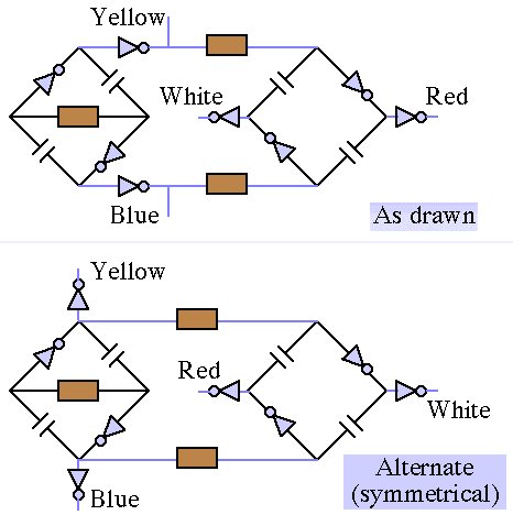
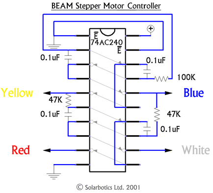
Some time back, Solarbotics sold some very nice little unipolar stepper motors. To drive them, Solarbotics came up with a nice simple drive circuit based on a master / slave bicore pair. It only drives the motor in one direction, but uses just a 74AC240 IC, four 0.1 uF capacitors, a 100 kOhm resistor, and two 47 kOhm resistors. You can, though, use this circuit to drive any bipolar or unipolar (via bipolar drive) stepper motor. In the Solarbotics diagram, the Yellow and Blue leads are the end contacts of one motor winding, and the Red and White leads are the end contacts of the other motor winding. In the case of the unipolar motor that Solarbotics sold, an additional two Green leads were the two windings' center taps, and left unconnected. |
|
I've drawn up schematics for both the circuit as designed by Solarbotics, and in a more symmetrical arrangement:

|
|
||
|
|
This page was last updated on |
|
