|
|
|
|
The BEAM Circuits Collection is a BEAM Reference Library site.
Steve Bolt's 4-transistor H-bridge
Design, limitations,
usage
Steve Bolt came up with an interesting 4-transistor H-bridge variant; this is cheap and easy to build, and best of all is "smokeless" (i.e., no combination of inputs can cause the bridge to self-destruct). Here's Steve's diagram:
You should bear the following things in mind with this design:
- 2N2905 and 2N2219 transistors
are no longer being produced; I use 2N2907
and 2N2222
transistors
in this circuit,
with good results.
- You absolutely must use one bias resistor
per transistor;
I attempted to simplify the circuit
by connecting the respective transistors'
bases (so each pair of transistors
could "share" a resistor)
-- this made for a circuit
that was simpler, much easier to freeform, and completely
non-functional.
- This efficiency of this design is driven by 2 things
-- the efficiency of the motor it's driving, and the size
of the bias resistors.
Just to make life interesting, these things are
interrelated (more on this later).
- This bridge is "smokeable" -- but only if power is
supplied to the bridge while the control inputs are
allowed to "float" (easy thing to avoid in your circuit
design).
- When I first started tinkering with this circuit, I made the assumption that the inverters pictured in Steve's diagram were not intrinsic parts of the bridge, but instead were examples of the outputs coming from the "driving" circuit. This is very, very wrong. If you don't include inverters (or, at least buffers) on the control inputs, you now have to take great care to avoid having the bridge influence the circuit that's driving it.
Since your circuit may or may not (and most likely, won't) have spare buffers / inverters available for use on the H-bridge control inputs, I've done some experimenting on the bridge circuit sans inverters -- let's call this variant "Bolt light."
|
If you want to build a "freeform" version of the "Bolt light" circuit, here's a very compact layout (note that this diagram shows the transistors in "dead-bug" fashion, i.e., with the chips "down," and their legs pointing up towards you). I've found it's easiest to solder the outside (motor lead) connections first, then the inside (Vcc / ground) connections, then the middle (resistor) connections. Note that two resistor leads "bridge over" the top of the transistor packages (these hidden leads are shown as dashed lines). |
 |
Built as a PCB
|
If you'd like to build your own "Bolt light" H-bridge circuit board, here's a life-size copy of the PCB "artwork." Note that I make my PCBs using transfer sheets, so the pattern is "mirror-reversed" from what the copper traces look like. An easier-to-follow, enlarged (x8) view of the PCB graphic is available here. |
|
|
Meanwhile, here's the parts layout for the PCB (here, shown from the "non-copper side" of the PCB ). |
 |
|
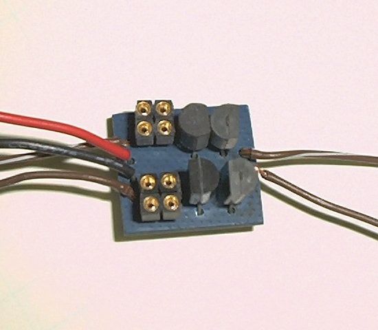
Here's the front of a populated PCB (in this case, with sockets for the bias resistors). |
 |
Performance
I've built the "Bolt light" circuit
using 2N2907
and 2N2222
transistors, and measured its performance (raw test data are
on a subsequent page).
I'm working on a "pretty" writeup, but in the meantime, here
are some things to bear in mind if you use this circuit:
- If you're not careful, the "control lines" can draw
enough current
to destabilize the Nv
net that's driving the bridge (I haven't quantified
how much current
has to be "sunk" in order to do this, it'll be a function
of the voltage
you're running at).
- Given poorly-selected combinations of motor and bias
resistance, this bridge can be horribly inefficient.
- This bridge should only be used for high-current motors (too large to be driven by "stacked" 74*245 chips); it has enough "personality" and a sufficiently-high parts count to make it a "special case" driver. I'd say it should be reserved for non-bicore circuits with high-current motors (and even then, used with great care).
|
|
||
|
|
This page was last updated on |
|