|
|
The BEAM Circuits Collection is a BEAM Reference Library site.
The "BEAM Stepper" drive circuit
A Duane C Johnson / Wilf Rigter
joint effort
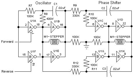
Duane Johnson and Wilf Rigter came up with this interesting 74AC240-based circuit to drive small bipolar stepper motors (e.g., the ones in floppy drives):

The 74AC240 stepper driver works by alternately enabling each half of the buffer. Only one half can be enabled at a time.
Let's assume that the top half of the driver is enabled. U1A & U1B along with R8, C1, and the input protection resistor R7 form a square wave oscillator. The outputs of U1A & U1B directly drive one coil of a bipolar stepper motor.
U1C & U1D along with R9, C2, & the input protection resistor R10 form a 90 degree phase shift. The outputs of U1C & U1D directly drive the other coil of the bipolar stepper motor. The motor turns in one direction.
If the bottom half of the driver is enabled, the oscillator using U1E and U1F work as before. U1H and U1G along with R12, C3, and the input protection resistor R11 form a 90 degree phase shift. Except it's connected the other way around from before so it's actually 270 degrees. The outputs of U1H and U1G directly drive the other coil of the bipolar stepper motor. The motor turns in the other direction. Neat, Huh!
For larger stepper motors, you should modify this circuit by adding H-bridges or similar drive circuitry (maybe a second 74AC240) to provide further motor current amplification.
|
|
|
|
|
|
||
|
|
This page was last updated on |
|