|
|
The BEAM Circuits Collection is a BEAM Reference Library site.
A 74*240-based motor driver
Design, limitations,
usage
A simple, time-honored approach is to use one or more 74*240 chips (normally the 74AC240 is used for maximum current capability) to provide motor drive current. Here, each channel of drive power is provided by one or more inverter on the chip.

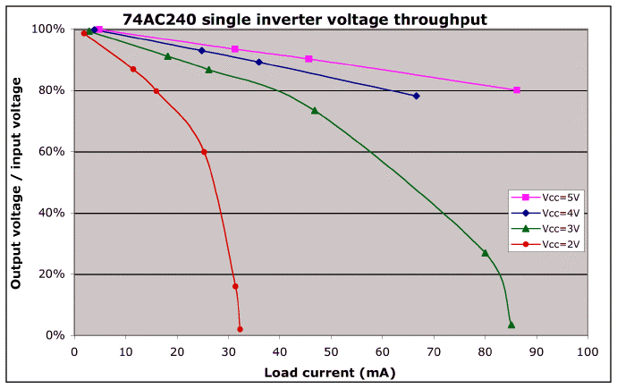
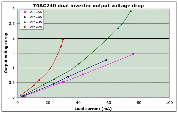
One of these chips can provide 8 individual drives, at up to about 35 mA per channel. Note that the available drive current is a function of both your supply voltage, as well as of the output voltage you can tolerate. To increase the available drive current, you can connect drivers in parallel or stack chips as needed.
The following plots show data from output testing of a single chip -- a Texas Instruments SN74AC240N:
Since the 74*240 is a 20-pin chip, it'll require 20 connections / PCB holes. Also note that this design is "smoke-proof." Best of all, since this chip has two separate enable lines, you can use this chip as a motor driver in designs that require one motor to reverse.
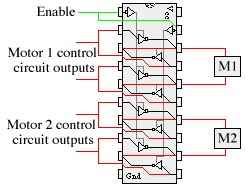 74*240 as a non-reversable motor driver |
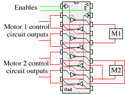 74*240 as a reversable motor driver |
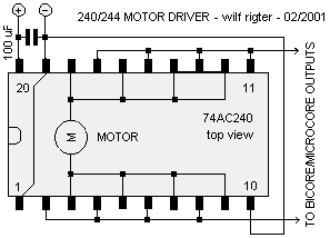
Alternately, if you don't need reversing capability, you can use the chip's inherent voltage drop to provide a 2-speed motor capability. Wire the two quads of inverters in parallel (i.e., in pairs consisting of one "A" and one "B" inverter each). Then by enabling neither set of inverters, a connected motor is braked; by enabling just one set of inverters, a connected motor runs at a low speed; by enabling both sets of inverters, a connected motor runs at a high(er) speed.
You can also use the chip as a simple single-motor driver:
|
|
||
|
|
This page was last updated on |
|

