|
|
BEAM From the Ground Up is a BEAM Reference Library site.
Leg mechanics
The tricky part
I can't possibly teach all the skills one needs to make an effective and efficient pair of legs, but with perseverance the following section should give you the right start. We will concentrate on a 2-motor / 4-leg walker which may not be the most flexible design, but is the easiest to build and has proven its reliability and capability in a number of existing machines.
1:
The motors This is probably the
biggest consideration in a microcore
Walker. The level of success
you have with your walker is directly related to
the type of motor used. The microcore
itself gets an implicit
feedback from the motors, this is what gives it the
adaptivity. What to look for in a
Motor.... 2:
The
gears You can't build a walker
without them. Most DC motors usually run far too
fast (1000's of RPM), and don't output enough
torque. What to look for in a
gearbox... 3:
Interfacing
motor and gears If you have to build your
own then bear a couple of things in
mind...... 4:
Materials Solder is our friend, and
the better your materials solder the easier it will
be to build a frame. Welding wire or filler rod is
the best bet. Copper clad carbon steel rod 1/6" to
3/32" diameter is cheap and available at any
welding supply place. An nice shiny option is High
Nickel filler rod used for TIG welding cast iron
but its MUCH more expensive brass tube and wire
found at most hobby shops is a good bet as well. I
suggest a solder with an Organic/water soluble
flux, "Hydro X"by Multicore is my
favorite. 5:
Basic frame
layout 6:
Adding the
legs Leg shape and
configuration will vary greatly between machines. A
few things to bear in mind are: Your legs will change
shape several times before you are done so its best
to make a set of "test"legs that are easily
recoupable before you use the good materials. 12 or
14 gauge household copper wire makes for effective
reconfigurable "Gumby" legs. 7
Making it
walk Time to make a minor
detour here ( you may have noticed we don't have
the microcore
connected to anything yet ).
Move on to the next section, Interfacing
the MicroCore With the Leg Motors
 This
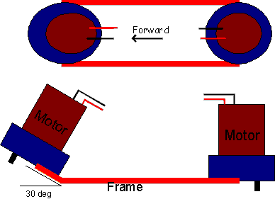
is the basic layout, you want to keep the motors
and output shafts lined up front to back and the
front motor should be tilted at 30 degrees. This
means the front motor will supply lift and push but
we'll discuss that more later. You should mount the
motors far enough apart to fit all your electronics
including batteries in between (usually about
4").


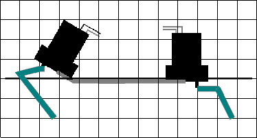
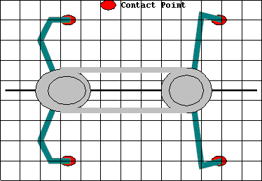
This is the most important aspect of leg design.
The shape of the leg is less important as where
it touches the ground. By placing you robot on a
sheet of graph paper as shown here you can get
symmetrical contact points.
Try to make the legs at least 2/3 the length of
your robot, this of course will depend on the
available torque. It has also been shown that
making the back legs slightly wider than the
front helps in stability
Make sure that your legs are connected with
something structurally sound, krazy glue doesn't
cut it. If you can't solder the legs directly to
the output shaft then try and find some sort of
locking ring or set screw that will fit. Look
for brass gears or pulleys that have their own
set screw and then you can solder the legs
directly to the brass.
By angling the legs slightly forward the legs
will have the ability to "ratchet" over
obstacles
|
|
||
|
|
This page was last updated on |
|
