|
|
BEAM From the Ground Up is a BEAM Reference Library site.
Applications
What to do with an Nv
net
Before you start on this material, you should have read the basic circuit page and built up a breadboard version. You've been warned...
|
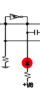
1: The basic circuit is just like a spinal cord without anything attached. You need some sort of clue as to what it is doing, so add low power LEDs to the output of each Nv. This makes it possible for you to see what's going on. You can't drive motors yet but until you are accustomed to the basic stable states of the microcore the motors will make even less sense than the LEDs. Note that here, only one Nv is shown, and the resistor should be at least 3 KOhm. |
|
2: Use a battery or very well regulated (i.e., low-ripple) supply. This is what you should get. This is know as the saturated state. This means all Nv's firing at Max rate. There is a maximum of 3 processes (a process is defined as one LED / Nv on) at any one time, so there will never be two adjacent LEDs on at the same time. This is the microcore's version of the Fermi exclusion principal, and an attribute shared by biological Nv nets. Saturation is the natural Power-on state. It is sort of the "crazy go nuts" state for a Nv Net. Saturation will occur when a the microcore encounters a disruption in main power, or when too much data is injected from sensors or Nu / Nv nets. Fortunately it's easy to get a more-stable useful state. |
|
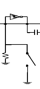
3:Add a Process Neutralization circuit (PNC). Wire up a switch to short out one of the input
bias resistors like this..... Closing this switch destroys any passing process. Hold it long enough and all processes are destroyed. Not really a good thing so.... |
|
4: Two process state By holding the switch closed for approx. 2
seconds you should be able to achieve
this.... If all values are even, and no feedback is available (say from a motor), then the processes should fall 180 degrees out of phase with each other. This is seen when they appear to be running side by side with each other. Two processes are sort of like Parkinson's disease the Nv's are trying to act against each other and if they fall into the 180 degree since then you have lock up (ever seen the movie "Awakenings"). This state can be useful in some cases but in the case of a simple walker its not much use. |
|
5: The single
process state By holding down the PNC switch for another 3 seconds or so you should get this. This is the stable one process state that is the basis of most of the Nv walkers. |
|
6: Null state A.K.A. Off, this is a Nv net at
rest. Kind of boring Huh.... |
|
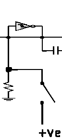
7: Adding a
Process Initialize Circuit (PIN) By wiring up another switch from an input to Vcc (+ve) you can introduce processes to the microcore. So by using the PNC and The PIN you should be able to cycle through all the microcore's usable states. |
|
8: Familiarization Time Now play with it, get used to it, understand it, and then go on to the Leg Mechanics section. |
|
|
||
|
|
This page was last updated on |
|

 Add
LEDs for visibility.
