|
|
BEAM From the Ground Up is a BEAM Reference Library site.
Core-leg interface
The brain-bone connects to the
leg-bone...
This section covers connecting the Nv net to the motors. What follows is a low current solution. High current motors and drives present a whole new set of problems that you don't want to deal with right now. Besides, the microcore does its best when driving through a low gain system.
|
1: Rethinking the Nv net By now you should have familiarized yourself with the basic 6 Nv microcore circuit. But a little math and you'll notice that with two motors and two directions each, 4 Nv's would seem appropriate. For basic walking function only 4 of the 6 available Nv's are needed in a two motor walker (although 6 makes for a whole new set of behaviors), so rebuild the basic circuit so you get this.... Have no fear the other two Nv's will be useful later... |
|
2: The
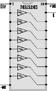
ALS245 The 74ALS245 is an Octal bus transceiver designed for data transmission. Well, we're going to use it to drive motors. If you've chosen you motor / gear combination properly then this won't be a problem. If you dig up a TTL data book you'll see that the 245 has 8 bidirectional non-inverting amplifiers each capable of driving 50 mA, a direction pin (Dir) for selecting which way through the chip and an enable pin (E).
|
|
3: Ganging up for Current If you've tested your motors you probably find that they need a little more than 50 mA to do anything useful [although this depends on your motors -- see here, Ed.]. And with a little math you'll see that there are 2 drivers available for each Nv, so gang them together like so....  The result is four drives capable of 100 ma each. Good but not great.... So if you need more, double your output by stacking a few chips...  |
|
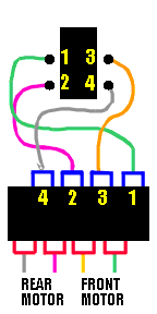
4: The connection So now you have a 4 Nv loop set up and a 4 channel driver set up. The next step is to glue em together and add the motors. Kinda' like so...  |
|
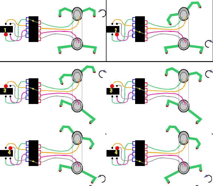
5: Power Up Power on the whole thing, stabilize the loop (one process), and you should get this:  If things aren't right change the motor polarity on one of the motors and it should work. |
|
6: Tuning for a walking gate A.K.A., Convergence |
|
|
||
|
|
This page was last updated on |
|

