|
|
BEAM Pieces is a BEAM Reference Library site.
Omron (Mac floppy drive eject)
gearmotor detailed data
All the data that's fit to
print
 |
 |
||
|
Comments
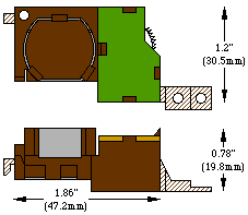
Floppy eject motors need to be "hacked" before you use them on a robot. I always cut off the cross-hatched pieces in the drawing above (just to minimize the motor's size). You definitely need to pry up the green circuit board and remove the small metal contact switch underneath it, as well as the one or two resistors on the circuit board. It's also cheap insurance to install a small (0.22 uF or so) filter capacitor in the resistor's place (across the motor's power leads). I have a detailed tutorial on all these steps elsewhere. These motors aren't quite as efficient as Nihon motors, but are very good for their size and cost. Since the starting voltage is relatively high for these guys (they're really not useable below 3.0 V), you'll most likely use these for battery-powered projects. |
|||
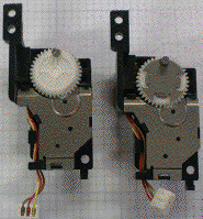
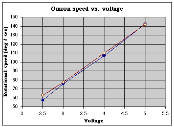
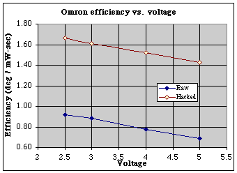
This page presents all the data from my testing of two examples of the Omron gear motor salvageable from Macintosh floppy drives. The test procedure I used is described in detail elsewhere.
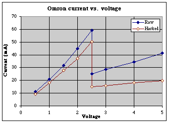
I tested two copies of this motor in two configurations -- with only minimal modifications (removal of internal "limit switch"), and fully "hacked" (two internal resistors also removed). The resistors (2 x 470 Ohm 1/2 watt resistors) are there to provide "dynamic braking" when the limit switch is tripped; in the motor's original use (i.e., to eject floppies), this makes sure that the motor stops at the same position, repeatedly. We don't need this function, so the resistors' waste of energy doesn't buy us anything.
What removal of the resistors does do is significantly increase the motor's efficiency, and decrease its current draw. But perhaps I should let the numbers speak for themselves...
Motor "raw" (minimal mods):
|
Voltage |
No-load Current (mA) |
No-load Speed (deg/sec) |
Efficiency (deg / mW-sec) |
|---|---|---|---|
|
|
|
|
|
|
|
|
|
|
|
|
|
|
|
|
|
|
|
|
|
|
|
|
|
|
|
|
|
|
|
|
|
|
|
|
|
|
|
|
|
|
|
|
|
Motor "hacked" (internal resistors removed):
|
Voltage |
No-load Current (mA) |
No-load Speed (deg/sec) |
Efficiency (deg / mW-sec) |
|---|---|---|---|
|
|
|
|
|
|
|
|
|
|
|
|
|
|
|
|
|
|
|
|
|
|
|
|
|
|
|
|
|
|
|
|
|
|
|
|
|
|
|
|
|
|
|
|
|
|
|
||
|
|
This page was last updated on |
|
