|
|
BEAM Pieces is a BEAM Reference Library site.
Stepper motors
Stepping your way
around...
As the name implies, stepper motors are different from run-of-the-mill DC motors, in that you make them move by sending them phased pulses of current, making the motor move in "steps." In order to do this, you need to send pulse trains of varying polarity to multiple windings, the speed of the motor being determined by the frequency of the pulses, and the direction of motor motion being determined by the phasing between the pulses being applied to the various windings. As a result, you get more-precise control over motor motion (vs. DC motors), but at the cost of some control circuitry complexity.
A number of types of stepper motors are available. As some are more common than others, I'll briefly discuss the ones you'll be most likely to run across, and most likely to be used in BEAMbots.
Permanent magnet stepper motors
The most common type of stepper motor you'll run across is
the permanent magnet (PM) stepper. As you might suspect from
the name, PM steppers have a permanent magnet in them -- in
the form of a rotor magnetized in alternate polarity
"stripes" parallel to the rotor shaft.
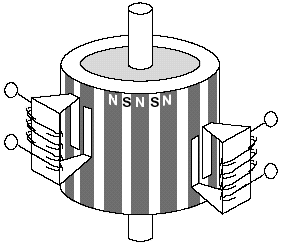
Permament magnet stepper motor layout (diagram courtesy Ericsson)
The step size (angular resolution) of a given motor is entirely a function of the angular "width" of these magnetized stripes -- 30 degrees is common, although steps down to 7.5 degrees are not unheard of in even very inexpensive motors.
Given this construction, you'll most often run into two different wiring configurations -- unipolar and bipolar. I'll start with the bipolar configuration since it's a bit simpler.
|
|
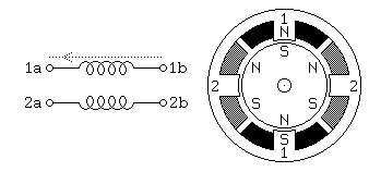
Bipolar stepper motors generally have four leads, in two pairs, each pair powering one coil. These motors are common and cheap -- as an example, the stepper motor that drives a floppy drive read / write head is a bipolar stepper motor. To rotate the motor, we simply supply the two coils with phase-shifted pulse trains. If you have no data on a given bipolar motor, you can identify which leads correspond to the windings of the motor with an ohmeter -- just check for continuity between the leads at the end of each winding.
|
|
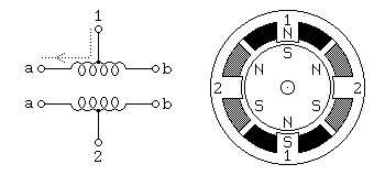
Unipolar stepper motors generally have six leads, in two triplets, each triplet powering one coil with a center tap . On occasion, you'll find a unipolar stepper with only five leads -- here the two "common" leads (center taps) have been tied together internally. Note that a unipolar motor's rotor is identical to a bipolar motor's rotor. Often unipolar motors are controlled by using the center taps as a common point (cathode or anode), and then just switching drive voltage from one end of the given coil to the other (to reverse coil polarity). This avoids the need for an H-bridge or similar motor driver. You can also drive unipolar stepper motors in a bipolar fashion (i.e. by just ignoring the center taps). If you have no data on a given unipolar motor, you will need to work a bit to find which leads correspond to each winding. Using an ohmeter, look for pairs of leads with equal resistance between them -- the common of each triplet will have equal resistance to two other leads, and high (essentially infinite) resistance to all the leads in the other triplet.
Controlling a stepper motor
Two control sequences for single stepping a unipolar or
bipolar stepper motor are shown below (here positive
voltages are denoted by red bars, and negative / ground by
blue):
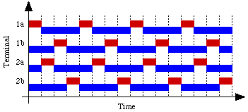
This first sequence only powers one winding at a time, so it provides lower torque at lower input power.
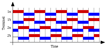
The second sequence powers two windings at a time and produces a torque about 40% greater than for the previous sequence while using twice as much power. From a circuitry perspective, though, producing this sequence is fairly simple (since the duty cycle is 50%, a master / slave bicore pair can be used, with some down-stream drivers, and potentially reversing logic).
|
|
|
Meanwhile, over in the PDF library, I'm mirroring some excellent PDFs on stepper motors, both from Ericsson: Stepper Motor Basics and Stepper Motor Drive Circuit Basics. Wilf Rigter devised an excellent single-chip BEAM controller for unipolar and bipolar stepper motors. This is a great circuit, and allows for motor reversing, but requires the use of a 74AC86 IC (which may not be in your parts box) -- I've got a small writeup on it in the Circuits library over here. Meanwhile, Solarbotics
has a single-chip (74AC240)
single-direction drive circuit
here;
I've also got a small (but growing!) writeup on it
in the Circuits
library over here. |
|
This site is offered to the public under the Open Content License. It may be redistributed or republished only under the terms of that license. |
||
|
|
This page was last updated on |
|
