|
|
|
|
The BEAM Circuits Collection is a BEAM Reference Library site.
Testing the Bolt 4-transistor
H-bridge
Results I've seen to
date
The following data results from measurements I took on a "Bolt light" 4-transistor H-bridge (sans inverters on the inputs), using 3 motors and 2 values of bias resistance. Note that the TS-53 data is "best estimate" data since (even with a 0.47 uF cap across the motor leads) motor current data for these hacked servos is very noisy. Note also that the majority of this data is useful even for a "full" Bolt H-bridge; even the Iq data is useful (it'll tell you if the inverters can source / sink enough current to drive the rest of the circuit).
Here's the raw data I collected:
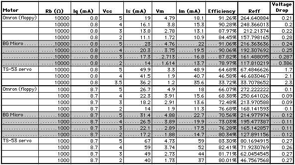
Here, Iq is the base sink / source current (for 1 NPN and 1 PNP transistor together), Is is the source current, Im is the current at the motor, Vm is the voltage across the motor. I compute efficiency as (Im * Vm / Is * Vcc); I'll talk about "Reff" in a bit.
Note that I'll be updating this table soon -- both to test with more values of Rb, and to better-characterize Iq (I only measured Iq at Vcc = 5 Volts, and assumed it would be the same for any voltage; Wilf pointed out that it will be a function of supply voltage as well).
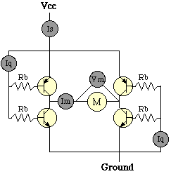
Anyway, here's the test configuration:
First I thought that efficiency may be a straight-forward function of voltage, so I plotted this mess:
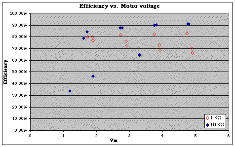
There's no obvious overall trend in the data, though each motor has its own trend. I then decided to follow up on a "hunch," and define a new parameter for characterizing a motor -- I call it (for the time being) "effective resistance," though I'm sure there's some better, official name for it -- it's just Vm / Im. I plotted this as a function of Vm (note that here Vm is on a logarithmic scale) for a couple of motors -- you can see that each motor has a characteristic curve, regardless of H-bridge configuration:
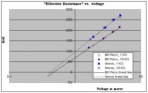
Note that for a given voltage, "less efficient" motors seem to have a lower "effective resistance." Wilf feels that the trend of Reff increasing with motor voltage is driven by motor EMF (via motor RPM); while I was sceptical at first, I now am sure he's right on this (no surprise!). Note that if you plot Reff vs. voltage for these motors when they're driven directly by a regulated power supply (no H-bridge), you don't get a logarithmic curve, but rather one that's almost linear with voltage. The motors are apparently having a big effect on the H-bridge's performance.
But I digress. Armed with this nifty new motor performance measure (Reff), I plotted H-bridge efficiency vs. motor "effective resistance" for the BG micro motor:
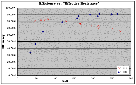
You can see a couple of interesting things in this plot (units of Reff are Ohms, BTW):
- There's a fairly pronounced curve for each set of
measurements
- Higher values of bias resistance in the bridge make
the bridge more efficient for more-efficient motors
- Less-efficient motors (like servos) prefer lower values of bias resistance in the bridge (tho' this means Iq will be higher).
Obviously, there's a trade-off of bridge efficiency vs.
"sink" current effects on the controlling (i.e., Nv
net) circuit; the moral of the story, though, is that in
some cases the value of bias resistance can be tuned to make
this bridge workable given the "right" combinations of motor
and Nv
net (without needing inverters on the inputs).
|
|
||
|
|
This page was last updated on |
|