|
The BEAM Circuits Collection is a
BEAM
Reference Library
site.
|
|
The Quad LED Fader (QLF) Family of
Circuits
The result of a running online
conversation between Wilf Rigter and Bill Bigge
The Quad LED
Fader family of circuits
was created by Wilf Rigter, essentially as his part of an
online conversation with Bill Bigge. This all started
innocently enough in the summer of 2003 with Bill Bigge's
query
about circuits
to drive some number of LEDs
or strings of LEDs
(nominally 4) in a random, independent, ornamental way:
I'm trying to put together a simple circuit
to fade a string of LEDs
on and off slowly. It needs to drive ten LEDs
in parallel
and turn them on and off slowly to give a nice slow
pulsating effect, all running off a 3v supply (2x AA
batteries).
|
Wilf's first reply
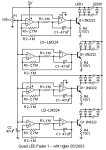
was with the QLF1 circuit
(click on thumbnail for a full-size diagram in a
new window):
Requires just 2 ICs
(LM324), 4 transistors,16
resistors,
5 caps,
1 pot and 40 LEDs.
That's 28 parts plus the 40 LEDs.
The circuit
consist of 4 triangle waveform generators
driving 4 current
sources. The LED
current
ramps linearly up and down and stays off for a
short time. Fade cycle time with R1 / C1 shown
is about 4 seconds as measured on my breadboard.
Adjust R1 / C1 as required to the 4 independent
frequencies.
I used just 3 LEDs
to simulate the string of 10 but the result
should be the same. Slowly adjust P1 from 0V up
to start oscillation and increase brighness. Too
high a P1 setting stops oscillation. You can
lower R4 if necesary if P1 adjustment is
insufficient.
|

|
|
A mere few hours later, Wilf
followed
up with a PWM (pulse width modulation) version
of the circuit
-- QLF2 (again, click on the thumbnail for a
full-size diagram in a new window).
|

|
|
As QLF2 did
not work very well, Wilf replaced
it with two designs -- an all-opamp PWM version
(QLF3) and a hybrid PWM version (QLF4):
|


|
|
 Subsequently,
Wilf posted
an explanation of the circuit
and its operation: Subsequently,
Wilf posted
an explanation of the circuit
and its operation:
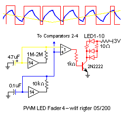
Attached is a section of the QLF4
circuit
and the relevant waveforms to match the
description of operation. The frequency of the
yellow triangular waveform is much normally
slower but is speeded up here to illustrate the
principle.
The left side of the circuit
consists of 2 74HC14 oscillators one of which
operates at 2 kHz and the other has a cycle time
of 2 to 4 seconds. The output pins of the
inverters
have squarewave outputs but the input pins have
a triangular waveform between 1V and 2V peak to
peak, which is the charge and discharge curve of
the capacitor
voltage
as it swings between the trigger and reset
thresholds of the Schmitt
inverter.
It is the BLUE 2KHz
input waveform and the
YELLOW slowly
changing reference voltage
we will use to generate the
RED Pulse Width
Modulation (PWM) waveforms that drive the
LEDs.
In the middle of the circuit,
one LM324 Quad opamp act as a comparator (a
LM339 can also be used with different pin out).
The + inputs of all comparators are connected to
the blue 2kHz triangular waveform while the -
inputs are connected to the respective yellow
~0.3Hz triangular waveforms of the slow
oscillators. The slow yellow waveforms are used
as ramping reference levels to which the common
blue 2kHz triangular waveforms are compared.
If the rising blue 2kHz waveform is more
positive than the yellow reference level, the
comparator output (red) goes high and supplies
base
current
to the output transistor.
If the falling 2kHz waveform drops below the
reference level the comparator output turns
off.
The yellow reference acts as a "slicing"
level through the blue 2KHz wavefrom and the
resulting red rectangular output waveform of the
comparator will be positive for a longer time if
the reference level is low and will be off
longer if the reference level is high.
The 2kHz rectangular waveform causes the
average current
through the 10 parallel LEDs
to smoothly change between 0 ma and 100ma or
from full off to full on and back again.
Since the four slow (Pulsar) oscillators all
have different cycle times, the four strings of
LEDs
will independently vary in brightness at
different rates. Peak current
can be as high as 400mA (all strings on) but the
average current
should be about 200mA, so AAA or larger alkaline
batteries
are required.
As for other applications, the LEDs
can be can be replaced with motors to provide
PWM speed control.
The reference voltage
level generated by the slow oscillators can also
be a potentiometer or a LDR
/ PD
photo bridge. The speed of the motors will be
variable and proportional to the voltages
at the reference level inputs.
|
|
 Within
a few days, Wilf had applied a bit more polish to
his circuit,
and posted
QLF5: Within
a few days, Wilf had applied a bit more polish to
his circuit,
and posted
QLF5:
Here is the polished up tested design,
Quad LED
Fader 5, which works on the same principle as
QLF4 but uses a LM339 quad comparator instead of
the LM324 quad opamp. The advantage is the LM339
has an open collector
output which permits rail to rail output signal
swing.
I have improved the QLF5 output drivers which
are now configured as 60mA current
sources to maintain even LED
brightness over a voltage
range of 3.2V to 2.4V when the battery
supply drops. The output current
is limited when the 2N3906 starts to turn on as
the current
through the 10 resistor
is about 50ma and the 2N3906 shunts base
current
away from the PN2907.
The 74HC14 oscillators now also have stable
output frequencies by regulating the chip
Vcc
line with a red LEDs
used as a 2V "zener".
The improved QLF5 circuit
is only slightly more complex using a total of
33 components in addition to the 40 LEDs.
However the perfomance is greatly improved over
the simpler QFL4 design.
The QLF5 can also be used with a 9V battery
for random rainbow cycling of tricolor LEDs.
With 3 LEDs,
one set of 6 components can be removed to reduce
parts count.
When the supply voltage
is increased to 9V or 12V, 3 or 4 LEDs
(or 3 or 4 groups of 3 LEDs
) can be driven in series for better matching of
brightness.
With a 9-12V battery
supply, the PN2907 1K base
resistors
must be increased to 10K and the 10 ohm
current
sensing resistors
should be made 33 ohm for 20mA current.
The 1K ohm resistor
in series with the 74HC14 Vcc line should be
raised to 10K.
|
|
 Wilf
was still able to improve on his circuit,
and posted
QLF6: Wilf
was still able to improve on his circuit,
and posted
QLF6:
Always aiming for the pure minimalist
design, here is QLF6, an amazingly simple but
effective 4 channel LED
controller which requires just 14 parts plus
LEDs.
This circuit
works nicely from 9V to about 2.4V with just
minor changes in brightness and frequencies. It
takes advantage of the build-in LM339 output
current
limiting.
The current
per output is about 20ma so several matched high
efficiency LEDs
can be driven in parallel. At higher supply
voltage
(9V max) use series LEDs
for higher efficiency and reduced LM339
heating.
PWM makes QLF6 efficient in part due to high
peak optical pulses which are perceived brighter
than the light of LEDs
operating at equivalent DC
current.
The oscillator frequency is stabilized with a
simple voltage
regulator across the 74HC14 chip power pins
using the forward voltage
drop of LED5. This also allows the circuit
to operate directly from 9V.
The slow oscillators that control LED
1-4 use non-critical resistor
values between 1M and 10M. The maximum values
shown give a maximum fade time for LED
1 of a few seconds.
The 100K pot can be adjusted from all
LEDs
OFF, to random flashing, to random fading, to
some weird stuff near the end of rotation. A
rainbow LED
connected to LED
1-3 can be used to [Ed.-- ???]
The QLF6 circuit
generates the full spectrum of colors and hues,
which is visually a much more appealing effect
than the recent Spectrummer design which only
generated pastel hues.
QLF6 is a true random fader / flasher as the
PWM switching transients seem to break up any
attempt of the oscillators to phase lock even if
the slow oscillators are close in frequency.
This circuit
can also be used to drive small motors to
generate some bizarre random motion, say no
more!
|
|
 A
few months later, Wilf revisited the QLF family --
making its behavior light-sensitive, and posting
QLF8. A
few months later, Wilf revisited the QLF family --
making its behavior light-sensitive, and posting
QLF8.
|
|


 Subsequently,
Wilf


