|
|
|
|
|
|
BEAM From the Ground Up is a BEAM Reference Library site.
All about torque
It gets your 'bot
going
The basics of torque
|
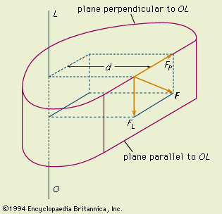
Let's start with the "official" definition from our friends at the Encyclopædia Britannica: Torque -- also called MOMENT OF A FORCE, in physics, the tendency of a force to rotate the body to which it is applied. The torque, specified with regard to the axis of rotation, is equal to the magnitude of the component of the force vector lying in the plane perpendicular to the axis, multiplied by the shortest distance between the axis and the direction of the force component. Regardless of its orientation in space, the force vector F can always be located in a plane parallel to the axis. In the figure, the force vector F lies in the plane parallel to the line OL; the component FL, being parallel to OL, has no moment about OL, while the component FP, lying in the plane perpendicular to OL, has a moment, or torque, about OL equal to FP * d, in which d, the shortest distance between FP and OL, is the moment arm or lever arm. |
|
So in short, torque is the combination of force applied at a point with the right angle (perpendicular) distance from that point to the axis of rotation (in our case, this'll be an axle). The formula to compute torque is simply this:
T = F * d, whereT = TorqueF = Force (here, the force applied perpendicular to the axis)
d = Distance
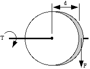
In 2 dimensions, you can visualize this simply:

So, if you had a pulley of 1 inch radius and a cord fixed to it with a 1 ounce weight hanging down on the end, it would produce 1 inch-ounce of torque on the pulley shaft (its axis):
T = F * d = (1 oz.) * (1 in.) = 1 inch-ounce
Bear in mind that we can also turn this all around. Given a value of torque, and the value of d (generally called the moment arm), we can also compute the tangential force that would be generated. Take our torque equation (T = F * d), and divide both sides of the equation by d:
T / d = (F * d) / dT / d = F
So we're now armed with two powerful equations to follow torque through a system of shafts, gears, pulleys, and the like. Before we get too far, you should be aware that we're making a few assumptions to simplify things:
a) Torque stays constant along a shaft (so we're neglecting any friction in bearings that hold the shaft in place).b) We're neglecting friction in our gears; a fairly accurate simplification for our applications. In particular, this means that force is the same on each gear at the contact point of two meshed gears (you'll see where this comes in later).
c) We can neglect the mass of any gears (the mass of gears only comes into play when they are particularly large, or particularly heavy -- both unlikely for BEAMbots).
Calculating Torque in a Geared
System
Now, using all this, how can you determine the
torque of a given motor in a geared system? Let's look at an
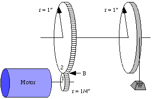
example with one pulley, and two meshed gears:

If we start at the pulley with a 1 oz. weight hanging off, then we have a torque on the top shaft of
T = F * d = (1 ounce) * (1 inch) = 1 inch-ounce of torque.
Now torque stays the same (we like to say "remains constant") all along the shaft so at the big gear (#2) it still has 1 inch-ounce of torque trying to turn it. What is the force at mesh point B?
Well, we can use the second version of our torque equation:
F = T / d = (1 inch-ounce) / (1 inch) = 1 ounce
Now, since the gear teeth are meshed, the force at point B is pushing on the smaller gear (#1) with the same 1 ounce force. Since we're neglecting friction, the force remains constant across the interface between gears.
Now, the torque on the motor shaft is just...
T = F * d = (1 ounce) * (1/4 inch) = 1/4 inch-ounce
So there is 1/4 inch-ounce of torque trying to twist the motor, thus the motor must be twisting with 1/4 inch-ounce torque to oppose it.
If we look at the motor's point of view, it's torque of 1/4 inch-ounce is magnified to 1 inch-ounce at the pulley. Cool, huh! The tradeoff is that the pulley turns slower than the motor (but I don't really want a bot zipping off the end of the table).
You can see that by applying only one formula T = F * d and it's algebraically rearranged form F = T / d, we can work our way through any geared system of this type.
If we know the motor's torque, then we can calculate the output torque on the final gear shaft (we could even find the horizontal force the wheel surface exerts on your tabletop). If we know the torque turning the wheels on your drive shaft, then we can back-calculate the motor's torque.
Calculating Motor Stall Torque
Imagine building a setup like this with a tube of
1 inch radius instead of just a pulley. You could have a
winch that you could attach weights to, to see what finally
stalls the motor. You could then back-calculate and find
your motor torque.
Start with a chain (like you pull to turn on a light), and it's sitting on the floor attached to the tube by fishing line, perhaps. As the winch pulls the cord, more and more of the chain rises and finally enough weight is pulling on the winch that your motor stalls. You could measure the height of the chain and multiply by the chain's weight per inch and you could calculate your torque value.
Chain weight W = X inches * 1/4 ounce per inchF = W since weight is a force
Then your motor's stall torque comes straight from our
old friend T = F * d (but you probably knew that!).
|
|
||
|
|
This page was last updated on |
|

