|
|
The BEAM Circuits Collection is a BEAM Reference Library site.
Sonic Output Indicator
Tom Grey's "sonic LED"
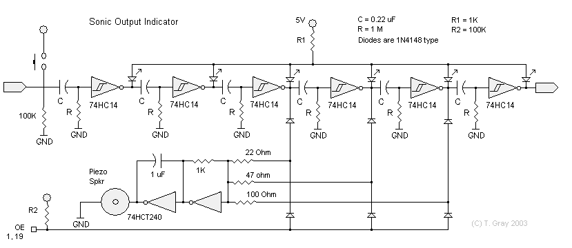
In a 2003 Yahoo BEAM list post, Tom Grey presented his sonic output indicator (intended as a replacement for an LED as a process state indicator):

I have been having fun linking a hexcore to Wilf's BEAM sound effects circuit--the two influence each other and make a most interesting mix of sounds. That got me interested in having sounds as output indicators, where we customarily use LEDs.I'm not entirely happy with it, as it runs at 80 mA even when it's quiet (the 6-Nv ladder [some people call this a 'spinal cord'?] uses 34 mA by itself) and it makes some pretty raspy square-wave type beeps, but it DOES work. I am always happy when I design even more-or-less works! 8^D Don't ask me *how* it works, I'm not there yet. I did discover that the diodes (1N418 type) are needed to keep the sound oscillator from resetting the process in the spinal cord. I also found that I couldn't use the last Nv in the ladder to hook to a sound or it sent the ladder into a frenzy, don't know why though.
You can tell where I'm headed--a noisy bot that chirps and chortles and whistles and snorts as it goes about its life. What I need is something of the cheerful whistles and warbles of Wilf's sound effects that will turn on in response to a Nv output, and remain quiet otherwise, without eating current. (I don't ask for much!)
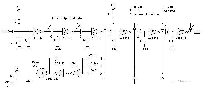
In a subsequent post, Wilf Rigter simplified the circuit slightly:

Well here is a quicky mod of your original circuit that should have much lower current.The audio oscillator modification fixes the high frequencies that were the main problem. The resistor cap values may be changed to suit. I suggest much larger resistors and smaller caps to reduce power.
The pushbutton input now gives one clean pulse to start the sequencer. A logic start signal can be coupled via the diode.
The 3 diode OR gate is changed to give a good logic signal for the tristate pin.
It should be much better behaved so that there is no disturbance of the sequencer operation allowing for more control resistors.
As you have probably found ourt by now, there are plenty of designs that make noise but only a few are pleasing to the ear and even fewer are worth listening to for any length of time. Those are the keepers.
I have no idea what your circuit sounds like so a small (?) audio file to the file section might be nice.
|
|
||
|
|
This page was last updated on |
|