|
|
The BEAM Circuits Collection is a BEAM Reference Library site.
Solar cell simulators
Test your 'bot with a
controllable "solar cell"
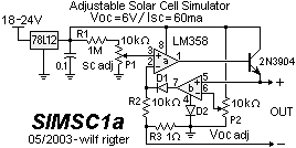
Starting with a post in May of 2003, Wilf Rigter published a series of solar cell simulator / battery charger circuits. The first design, SIMSC1 was quickly revised in a later post:

Wilf describes this circuit as follows:
The 78L12 provides the regulated voltage required at the input of the solar cell simulator. It limits the voltage to 12V and the current to about 100ma. A 15V-24V unregulated voltage is used as the input to the 78L12. Any other regulated 9V-12V source can be used.The LM324 is a quad opamp of which only two sections are used. A LM358 dual opamp (8 pin) can also be used. One opamp is used as a current source with the 0-60mV Isc reference voltage as one input and adjusts the opamp output current ("+ out") until the voltage drop across the 1 ohm resistor (shunt) is equal to the reference input. The second opamp uses a 0-6V Voc reference as one input and monitors the "+ out" voltage on the second input. When the "+ out" voltage is equal to the reference, the second opamp output applies a positive voltage to the current source inverting input causing the current source output to drop while maintaining the "+ out" equal to the Voc reference voltage.
The net result is a constant charging current up to Voc-Vshunt and a rapid tapering off as the "+ out" voltage is limited to Voc.
SIMSC1a adds D2 so that the output current starts at 0 ma. Since the LM358 opamp output current was limited to 30ma I added an NPN output transistor to provide up to 100ma of current. I tweaked some component values for the wider output current adjustment range.
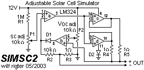
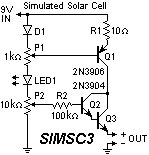
A few days later, Wilf posted two additional designs:
SIMSC2 uses a LM324 with two opamps in parallel to boost the output current to 60mA. The 1 ohm resistors help to share the current.

SIMSC3 shows a simpler but less accurate discrete version of a solar cell simulator. It uses the relatively stable voltage of a "fresh" 9V battery as the "reference", however the current and voltage adjustment will drift when the battery voltage drops. For small currents (<10ma), a fresh 9V alkaline battery should be good for many hours.

|
|
||
|
|
This page was last updated on |
|