|
|
The BEAM Circuits Collection is a BEAM Reference Library site.
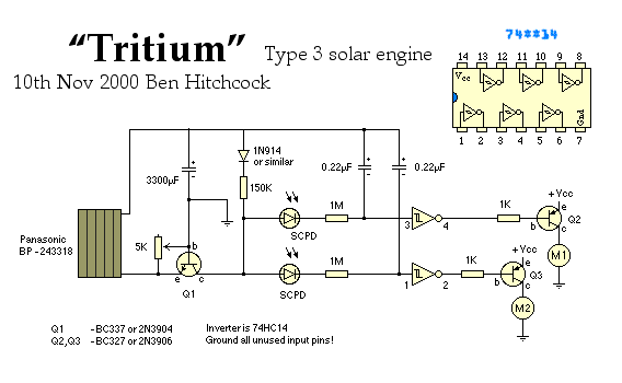
The "Tritium" type 3 solar engine
Ben
Hitchcock 's take on a type 3
solar engine

Ben's comments on his design:
The Tritium circuit was the first (to my knowledge) type
3 SE. As such, it is quite experimental, and should be
regarded as a prototype rather than the 'state of the art'!
Nevertheless, it does function reasonably well, and in some
circumstances outperforms other solar engines such as the
Freds that I have lying around.
It works by charging the capacitor through the base-emitter junction of an NPN transistor (Q1). When current is flowing through this junction, the collector is held low. When the charging current tapers off, the collector will start to drift higher pulled positive by the diode and 150k resistor, until it reaches the trigger point of the 74HC14 at which time the solar engine will fire. The pot across the base-emitter junction 'steals' a portion of the charging current, making the transistor more likely to turn on with a given charge current. Adjustment of this pot is a bit fiddly and usually ends up with the SE 'tuned' for a given light level.
The little SolarCellPhotoDiodes generate a small voltage across them, which turns on one gate before the other, allowing the Tritium to be able to turn towards the light and slowly tick its way towards the brightest part of its environment. Note that this circuit is designed to fire two motors in the standard 'photopopper' or 'Fred' arrangement (unlike the T3SE which fires one motor).
The potentiometer as shown has one pin that is floating around doing nothing. You can connect this to ground if you feel like it, but this won't make that much difference.
To adjust this pot, put your tritium popper in the brightest sunlight that it is likely to face, set the pot to maximum resistance, let the popper charge up fully, then slowly decrease the resistance until the popper pops.
Your tritium popper is now adjusted properly :-)
Wilf Rigter's comments on this design:
The Tritium circuit is closely related to the one transistor
SIMD1 V2 circuit that
uses the base emitter junction of a NPN
(or PNP)
transistor to charge the main capacitor and to sense a drop
in the Solar cell output and used the collector voltage to
trigger a Schmitt
inverter. The base emitter resistor used in the Tritium
circuit is used to set the trigger level proportional to a
minimum charging current. The high voltage gain of this
common base amplifier magnifies the slope of the charging
current and causes the collector voltage change relatively
rapidly. One problem with the Tritium is that during the
discharge of the main cap into the motor load, the charging
current increases again and the transistor turns on and
shuts off the Tritium cicuit.
The pot in the Tritium circuit is used to set the current at which the SE triggers. Since the current is initially high when the capacitor starts to charge from zero volts and then tapers off towards the end of the charging curve, a current level can be set, below which the SE triggers.
That imposes a restriction since the current level pot must be set to sense current lower than the minimum short circuit current which a solar cell generates at the lowest light level of interest or else the SE will just stay on.
In other words, set the current trigger level too high and the SE won't pop in low light, set the current too low and the SE will take a relatively long time to charge a cap.
|
|
|||
|
|
|
|
|
|
Storage capacitor |
|
|
|
|
Solar cell |
|
|
|
|
1 KOhm resistor |
|
|
|
|
150 KOhm resistor |
|
|
|
|
1 MOhm resistor |
|
|
|
|
5 KOhm var. resistor |
|
|
|
|
0.22 uF capacitor |
|
|
|
|
1N914 diode |
|
|
|
|
Photodiode |
|
|
|
|
2N3904 transistor |
|
|
|
|
2N3906 transistor |
|
|
|
|
74HC14 IC |
|
|
|
|
|
||
|
|
This page was last updated on |
|