|
|
|
|
The BEAM Circuits Collection is a BEAM Reference Library site.
Wifl Rigter's SIMD1 V0
Part of a family of nocturnal
solar engines (all circuits on this page ©
Wilf
Rigter ; note that the majority
of this explanatory text comes from either postings by, or
correspondence with Wilf)
SIMD1 V0 is the original SIMD1 design, and is based on a simple concept -- charging the storage capacitor through a Ge diode (for minimum forward voltage drop).
 |
 |
|
|
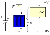
e = enable (active low); v = Vcc; g = Gnd |
LED load with gate driving enable |
A resistor (here shown as 1MOhm, but can be as small as 100KOhm) is connected in parallel with the solar cell for two reasons:
- It provides much quicker turn-on when the Sun goes
down. Note that a smaller value for the resistor
will provide faster turn-on; the trade-off is that a
smaller value for the resistor
also makes the solar engine less efficient at charging
the capacitor
(since we're then losing more of our precious solar power
through resistive losses in daylight). In any event, the
SIMD1 V0 requires almost complete darkness in order to
trigger.
- It acts as a "pull-down" resistor to provide a discrete indication of when things are dark enough for the load to come on. Essentially, this means that the solar cell is used as a light sensor (incidental to its function of charging the storage capacitor).
|
|
|||
|
|
|
|
|
|
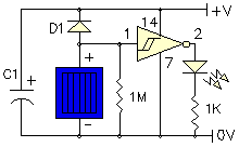
Storage capacitor |
|
|
|
|
Solar cell |
|
|
|
|
Germanium diode (1N34A) |
|
|
|
|
1 MOhm resistor |
|
|
|
In the example circuit, the SIMD1 V0 is shown driving a single LED, which is of course a trivial example to demonstrate the basic solar engine circuit. The example takes advantage of the fact that HC logic is made with FETs so why bother using an additional discrete FET to drive a load? So here the V0 output is connected to a CMOS gate input. The Schmitt trigger is just an example of "the rest of the circuit" albeit a special case because of the fast switch-over due to input hysteresis. More importantly, the CMOS input threshold drops as Vcc drops which reduces the effect of the dropping capacitor voltage during discharge.
Normally the active high output from the inverter is used to enable the remainder of the CMOS gates which then perform some useful function. When the SIMD1 triggers at night, it snaps on and the output signal can be used to control the 5 remaining 74HC14 inverters connected in parallel with the outputs used as a "power" switch. Or the signal can be used as the tristate control of a 74HC240 or 74HC245 or be used as a PNC input for an Nv net, etc. to apply the stored energy to the load.
A point to remember when adding on the rest of the circuit is that CMOS logic draws considerable supply leakage current when inputs are not at 0V or Vcc. That problem virtually disappears when Vcc <3V; as a result, this circuit is only useful with a single 2.5V capacitor and a lower voltage solar cell. Also note that the example circuit also has a somewhat high switching voltage when the difference between the solar cell voltage and the capacitor voltage is sufficient to turn on the CMOS gate. A 74HC14 switches at a difference voltage of 2/3 Vcc. In general, HC logic switches at 1/2 Vcc and HCT logic around 1.8V.
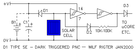
A variant of this circuit can also be used to provide a dark-driggered PNC. Note the 100 ohm positive feedback resistor loading the solar cell only after the SIMD1 turns on, this can be adjusted to optimize the SIMD1 turn off point. The output diode is connected in place of the usual PNC in an Nv net circuit.
|
|
|
|
|
|
||
|
|
This page was last updated on |
|